Weight plate with center post locking cartridge and locking fork

a technology of locking cartridge and weight plate, which is applied in the field of weight plate, can solve the problem that the weight plate is unlikely to be uncoupled

Active Publication Date: 2016-05-17
CORE HEALTH & FITNESS
View PDF9 Cites 31 Cited by
  • Summary
  • Abstract
  • Description
  • Claims
  • Application Information

AI Technical Summary

Benefits of technology

[0009]According to a preferred embodiment of this invention, when the switch control knob is rotated in a first direction, the toggle lever switch arm is correspondingly rotated to the locked position. In this case, the fork carried by the switch arm is moved through the intermediate channel of the weight plate body and into locking engagement with the center post of the weightlifting equipment at the center bore hole, whereby the weight plate is coupled to and lifted by the center post along with a stack of similarly coupled weight plates during a lifting exercise. Each of the pair of fingers of the fork is sufficiently long so as to extend completely through the center bore hole and into the finger locking cavity lying opposite the intermediate channel. With the fingers of the fork received within the finger locking cavity, a structural reinforcement is advantageously provided to help prevent the inadvertent detachment of the fork from its locking engagement with the center post as the weight plate is lifted in response to an upward lifting force applied to the center post. Therefore, the weight plate is unlikely to be uncoupled from the center post throughout the exercise.

Problems solved by technology

Therefore, the weight plate is unlikely to be uncoupled from the center post throughout the exercise.

Method used


Image

  • Weight plate with center post locking cartridge and locking fork
  • Weight plate with center post locking cartridge and locking fork
  • Weight plate with center post locking cartridge and locking fork

Examples


Embodiment Construction

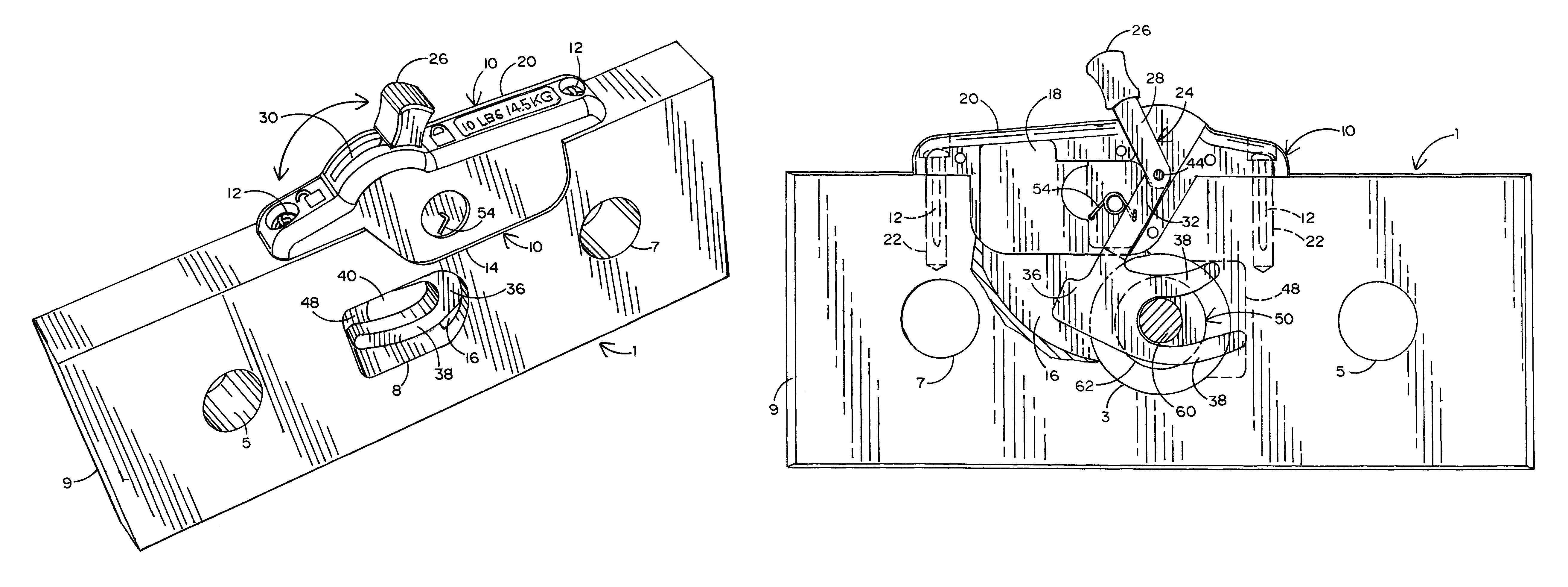
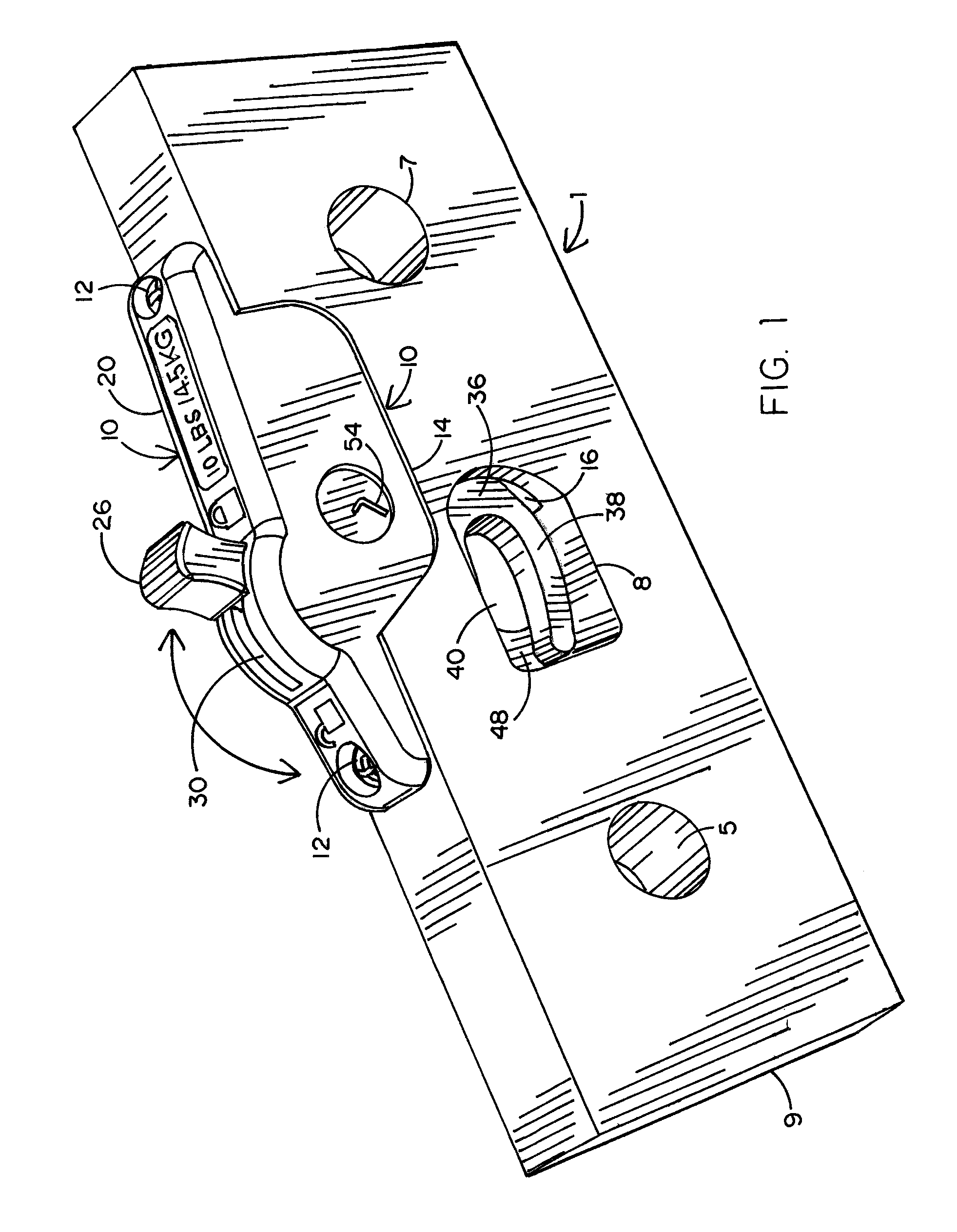
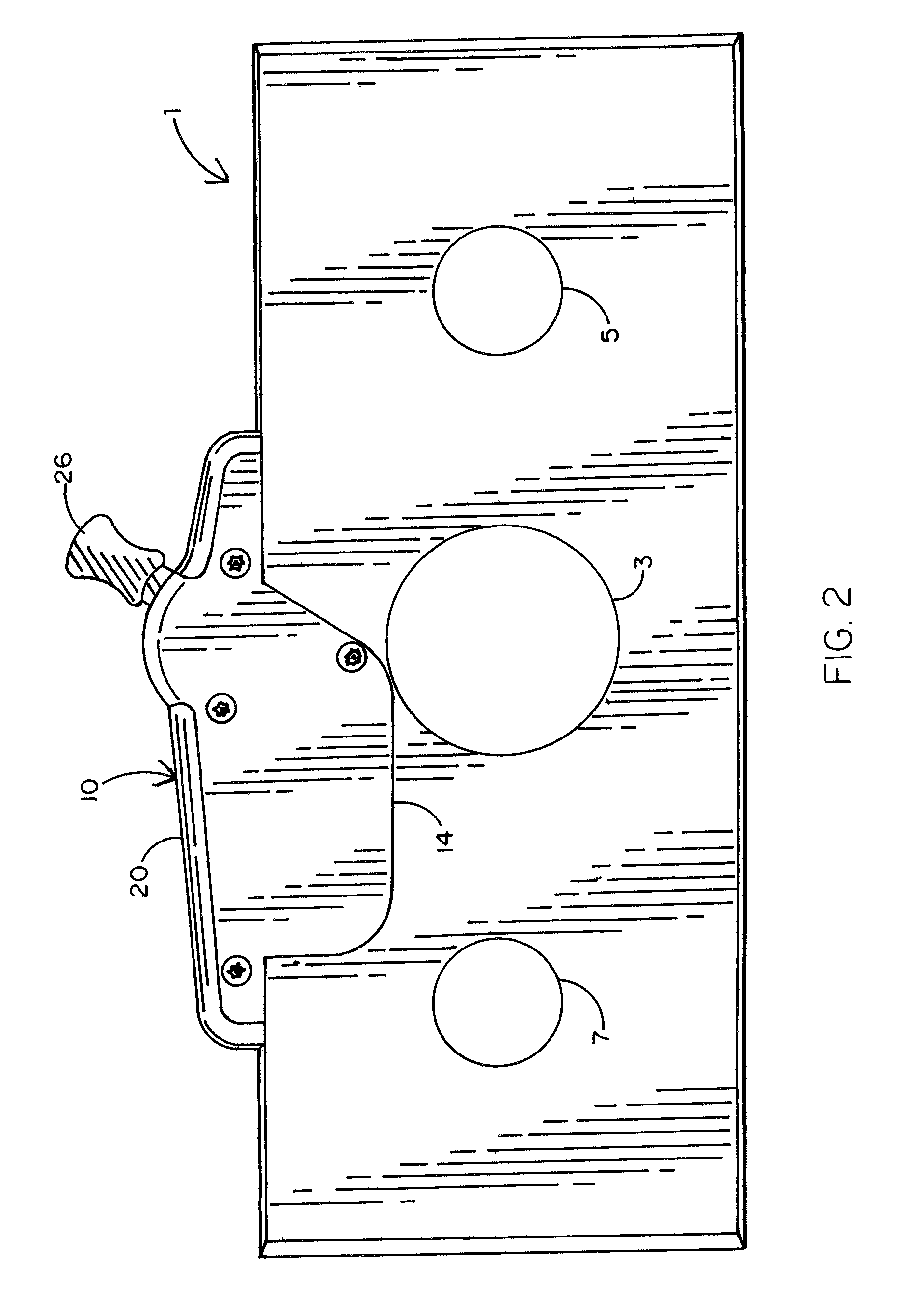
[0017]Referring concurrently to FIGS. 1-4 of the drawings, there is shown a rectangular weight plate 1. The weight plate 1 has a round center bore hole 3 and a pair of round side bore holes 5 and 7. Each of the center and side bore holes 3, 5 and 7 extends completely through the weight plate 1. The round center bore hole 3 is sized to accommodate a conventional cylindrical center post (designated 50 and best shown in FIGS. 3-6) of the kind used by a typical weight plate lifting exercise apparatus. The round center bore hole 3 expands to a larger elliptical shape 8 at the bottom of weight plate 1 (best shown in FIG. 1). In the case where the weight plate 1 is one of a vertical stack of weight plates located one above the other, the center post 50 extends continuously and axially through the center bore hole formed in each of the weight plates in the stack. The side bore holes 5 and 7 are located at opposite sides of the center bore hole 3 and sized to accommodate respective cylindric...


PUM


Abstract

A weight plate for physical fitness weight lifting equipment so that the weight plate may be coupled to other weight plates and lifted in a stack. The weight plate includes a pivotal switch arm having a first end at which to receive a pushing force to cause the switch arm to rotate and an opposite end at which a fork is carried. A post runs through a center bore hole of the weight plate. The weight plate also includes an intermediate channel and a locking cavity that are aligned with one another at opposite sides of the bore hole. When the pivotal switch arm is rotated to a locked position, the fork is rotated through the intermediate channel, into surrounding engagement with the center post, and completely through the bore hole for receipt by the locking cavity by which the weight plate is reliably coupled to the post.

Description

BACKGROUND OF THE INVENTION[0001]1. Field of the Invention[0002]This invention relates to a weight plate adapted to be selectively coupled to the center post of physical fitness weightlifting equipment so that one or more weight plates may be lifted by the center post during a body-building exercise. The weight plate includes a locking cartridge having a fork that is carried by a rotatable toggle lever switch arm so that a pair of fingers of the fork are moved (i.e., rotated) from an unlocked position to a locked position for receipt by a finger locking cavity formed in the weight plate body, whereby the fork is reliably coupled to the center post.[0003]2. Background Art[0004]My U.S. Pat. No. 7,608,021 issued Oct. 27, 2009 discloses a weight plate that is associated with weight lifting equipment by which the weight plate or a stack of weight plates can be lifted during a body building exercise. This weight plate includes a plate body and a locking cartridge connected to the plate bo...

Claims


Application Information

Patent Timeline
Patent Type & Authority Patents(United States)
IPC IPC(8): A63B21/06A63B21/075A63B21/072
CPCA63B21/0728A63B21/075A63B21/063
Inventor NALLEY, MARK
Owner CORE HEALTH & FITNESS
Why Eureka
Try Eureka