Dispenser with child-proof lock

a dispenser and lock technology, applied in the field of dispensers, can solve the problems of comparatively high manufacturing cost of child-proof dispensers, and achieve the effect of sufficient deformation of the locking devi

Active Publication Date: 2016-05-31
APTAR RADOLFZELL
View PDF31 Cites 6 Cited by
  • Summary
  • Abstract
  • Description
  • Claims
  • Application Information

AI Technical Summary

Benefits of technology

[0009]According to a first variant of the invention, such a dispenser is provided with a protective device or child-proof lock that consists of at least two, and preferably exactly two, partial shells which in a protective condition are connected to one another by at least one coupling device for repeated decoupling and coupling in such a manner that they are immobilized relative to another. Thereby, the protective device is attachable to the feeding device of the dispenser in a protective position such that in the protective condition of the protective device with securely connected partial shells the accessibility and / or maneuverability of the actuating handle is prevented. Only upon releasing the coupling device an enable condition of the protective device is achievable, wherein the partial shells are displaceable relative to another so that the protective device previously surrounding the feeding device is removable from the feeding device, and thus accessibility and / or maneuverability of the actuating handle is obtainable.
[0033]The locking device may be an integral constituent of the actuating handle and be formed in one piece with the handle. Optionally, with such a configuration it may be an advantage to produce said component constituting the actuating handle and the locking device by two-component injection molding, to ensure sufficient deformability of the locking device.

Problems solved by technology

However, such child-proof dispensers are comparatively expensive to manufacture, since the partial components thereof are for the most part not adaptable to other possibly non-child-proof dispensers, so that specific tools are required for most of the components of such child-proof dispensers.

Method used


Image

  • Dispenser with child-proof lock
  • Dispenser with child-proof lock
  • Dispenser with child-proof lock

Examples


Embodiment Construction

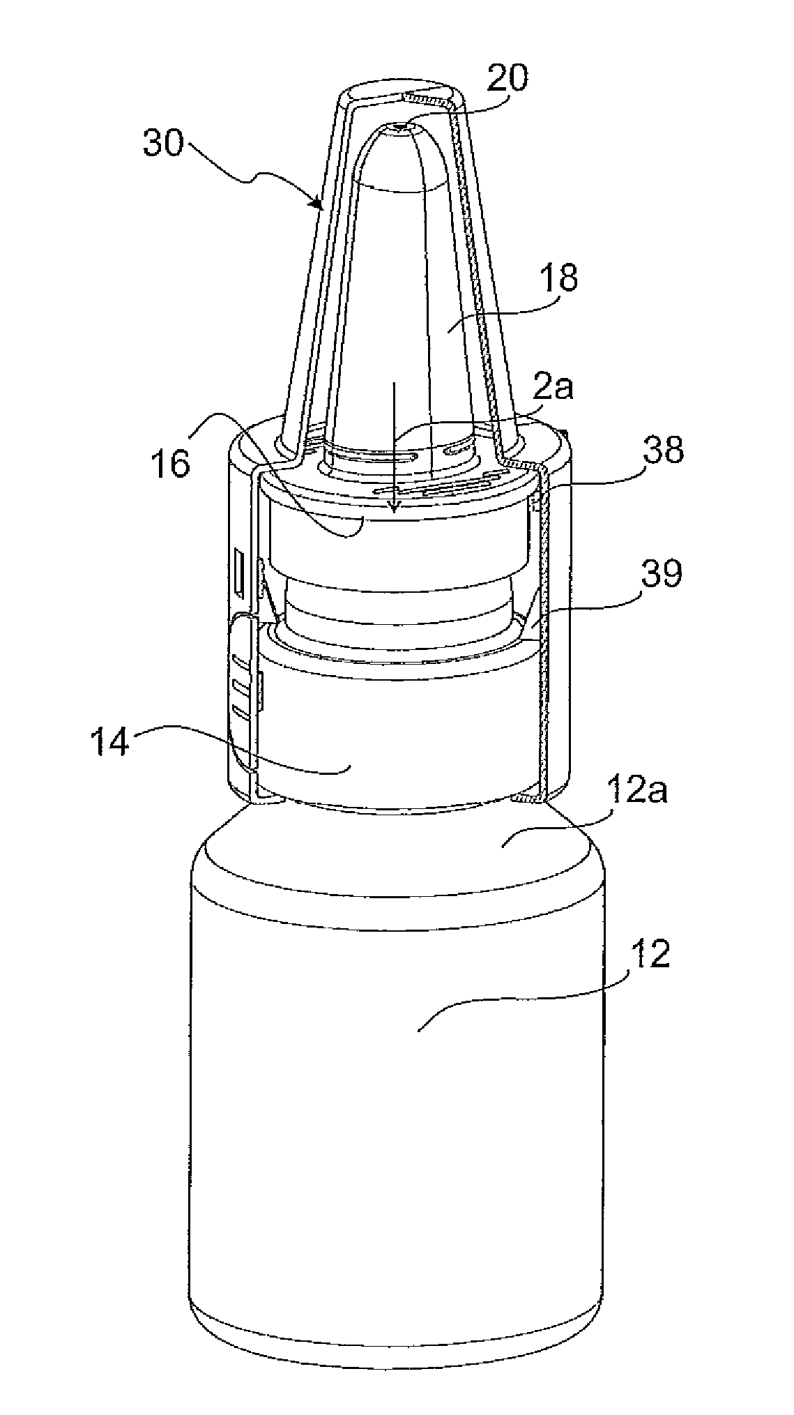
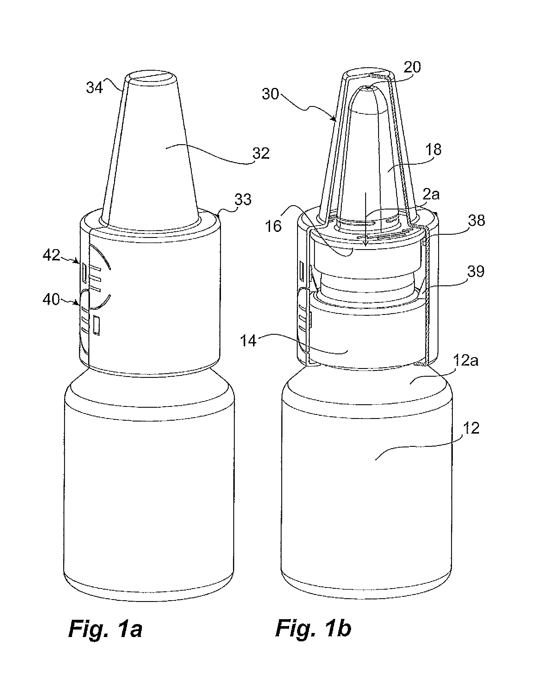
[0045]FIGS. 1a and 1b show an embodiment of the first variant of the invention. Referring to the partial sectional view of FIG. 1b, a dispenser is used which is comparable as regards the basic structure thereof to well-known dispensers. Said basic structure comprises a medium reservoir 12, a feeding device 14 attached on a neck 12a of the medium reservoir 12 including an actuating handle 16 for actuating the feeding device 14, and a discharge opening 20 in the present case provided on the distal end of a nose olive 18. By displacement of the actuating handle 16 in the direction of the arrow 2a, a piston pump, not illustrated in detail, provided within the feeding device 14 can be activated to feed liquid medium from the medium reservoir 12 to the discharge opening 20.

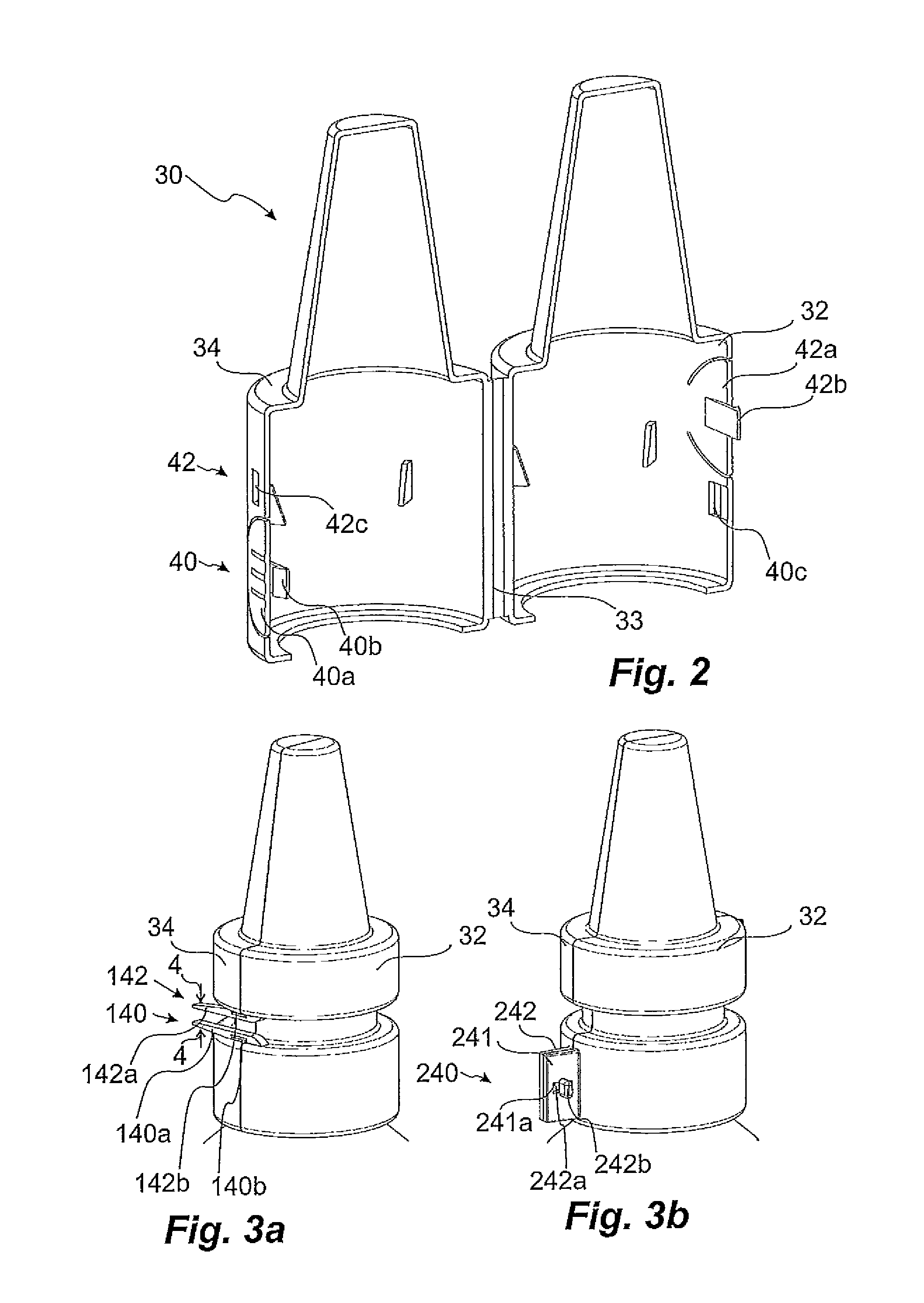
[0046]To prevent any improper use of the dispenser by children, a protective device 30 is provided. Said protective device 30 includes two partial shells 32, 34 interconnected by an integral hinge 33. In the manner as i...


PUM


Abstract

A dispenser including a medium reservoir, a discharge opening, and a feeding device for feeding medium from the medium reservoir to the discharge opening, wherein an actuating handle is displaceable relative to the medium reservoir in an actuation direction to discharge medium.The dispenser includes a protective device with two partial shells interconnected in a protective condition by a coupling device for repeated decoupling and coupling wherein the protective device is attachable to the feeding device in a protective position such that in the protective condition the accessibility and / or maneuverability of the actuating handle is prevented, and upon releasing the coupling device an enable condition of the protective device is achievable in which the partial shells are displaceable relative to another so that the protective device is removable from the feeding device, and thus accessibility or maneuverability of the actuating handle is obtainable thereby.

Description

CROSS REFERENCE TO RELATED APPLICATION[0001]This claims priority from German Application No. 10 2012 218 434.1, filed Oct. 10, 2012, the disclosure of which is hereby incorporated by reference in its entirety into this application.FIELD OF THE INVENTION[0002]The invention relates to a dispenser for discharging a liquid or pulverulent medium comprising a medium reservoir, a discharge opening, and a feeding device for feeding of medium from the medium reservoir to the discharge opening. Therein, such a dispenser has an actuating handle of the feeding device, displaceable relative to the medium reservoir in an actuation direction to thereby effect a discharge of medium.BACKGROUND OF THE INVENTION[0003]Such dispensers are generally known from the prior art. As an example, reference is made to DE 10 2004 050 679 A1 disclosing a nasal dispenser.[0004]Such dispensers are used for discharging pharmaceutical media. It is often desirable to hinder accessibility of the medium for children so t...

Claims


Application Information

Patent Timeline
Patent Type & Authority Patents(United States)
IPC IPC(8): B05B11/00A61M15/08
CPCB05B11/3059B05B11/0027B05B11/0032A61M15/08A61M2202/064A61M2205/276B05B11/1059A61M15/0001
Inventor GREINER-PERTH, JUERGEN
Owner APTAR RADOLFZELL
Why Eureka
Try Eureka