Distribution array for use in a settler area of a mixer-settler

a distribution array and settler technology, applied in the field of distribution arrays, can solve the problems of increased operating costs, loss of extraction efficiency, and difficulty in managing the flow of liquid in settlers, and achieve the effect of minimising the impact of dynamic head loss

Active Publication Date: 2016-07-05
HATCH PTY LTD
View PDF15 Cites 0 Cited by
  • Summary
  • Abstract
  • Description
  • Claims
  • Application Information

AI Technical Summary

Problems solved by technology

It is difficult to manage the flow of liquid in settlers to achieve sufficient separation of the various liquid phases and to minimise the settler area that is required to effect separation of the phases.
The flow of liquids needs to be as laminar as possible, as flow interruptions or turbulence can lead to co-mixing of phases and resultant losses in extraction efficiency.
Poor phase disengagement as a direct impact of turbulent flow also leads to, significantly higher solvent losses resulting in higher operating costs and significantly higher aqueous carryover resulting in final product impurity control issues.
The settling stage allows the phases to separate, but achieving high flow rates can disturb the flow and hamper the process of separation, making it inefficient.
However, such conventional distribution systems create recirculating zones and dead zones within the settler, in which fluid does not flow or flows in an unintended direction, often the reverse direction.
In conventional systems of which the Applicant is aware, feed distribution baffles are positioned in the feed streams in the settler area in an attempt to effect an even flow, but these systems do not produce a suitably even distribution of fluids at higher flow throughputs.
A common problem with such baffles is that they are highly susceptible to scaling, leading to significant down-time and process interruption for cleaning or replacement of baffle elements.
Other systems of which the Applicant is aware include fixed obstacles or deflector plates placed within the settler area, but these systems have significant drawbacks in terms of settler kinetics and flow dynamics.
So-called split launders and variable-split launders have also been used in certain systems, but these are also of little value in ensuring smooth fluid flow and dispersion distribution.

Method used


Image

  • Distribution array for use in a settler area of a mixer-settler
  • Distribution array for use in a settler area of a mixer-settler
  • Distribution array for use in a settler area of a mixer-settler

Examples


Embodiment Construction

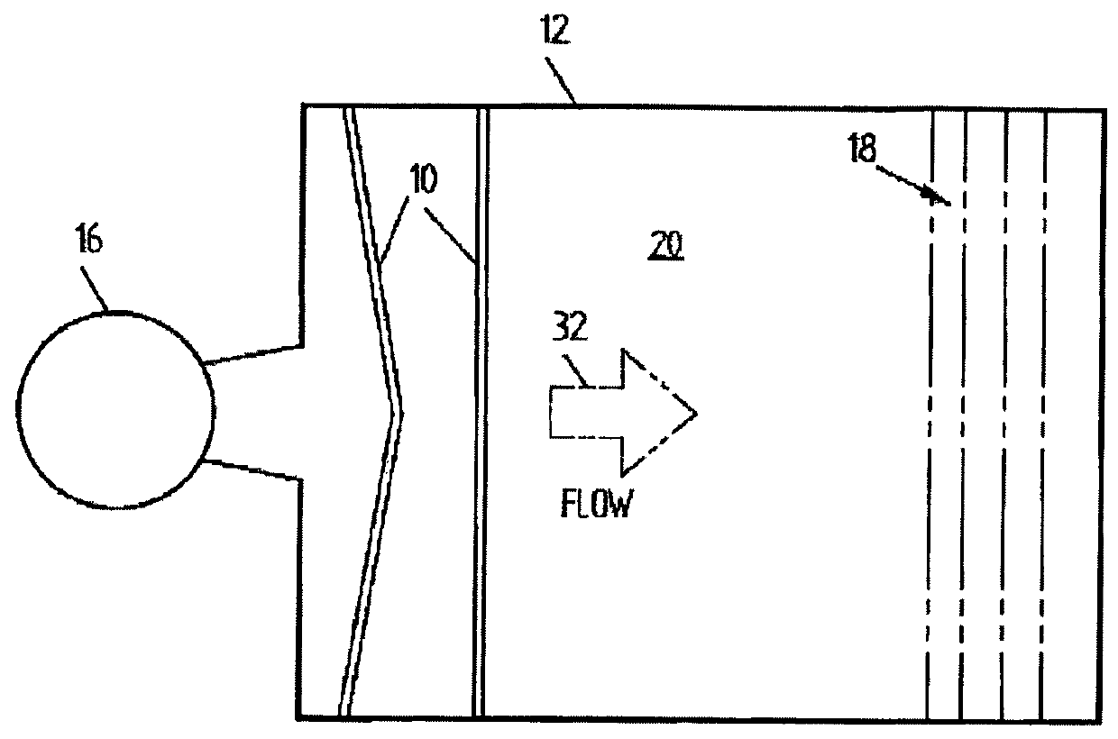
[0042]The Applicant has investigated the transverse nature of flow patterns in settlers and has identified and analysed pressure gradients which were found to develop in the conventional feed systems used therein. CFD (computational fluid dynamics) was the principal tool utilised to evaluate feed distribution systems, while quantitative distribution measurement was utilised to rank each system that was tested.

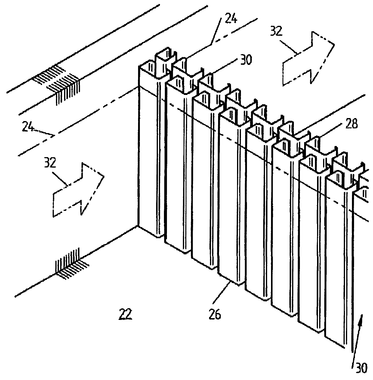
[0043]The distribution array of the present invention as described herein defines fluid flow channels or slots for feed fluids to flow through. The channels are defined by barrier elements provided as panels of such barrier elements, wherein the fluid flow channels between the barrier elements are longer than they are wide, relative to a length of the settler area in which the panel is to be positioned or is located. This greatly reduces any transverse fluid flow in the settler area subsequent to the distribution array.

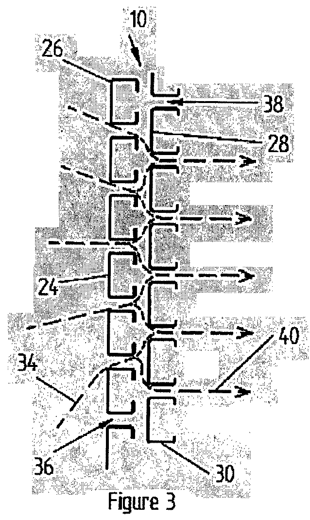
[0044]It was found that variation in the spacing between th...


PUM

PropertyMeasurementUnit
depthaaaaaaaaaa
depthaaaaaaaaaa
cross-sectional widthaaaaaaaaaa

Abstract

A distribution array (10) for use in a settler area (12) of a mixer-settler, the distribution array (10) characterized by: at least one panel (26, 28) of linearly-spaced barrier elements (30), wherein the depth of the barrier elements (30), relative to a length of the settler area (12) in which it is to be positioned, is greater than the spacing between the barrier elements (30), thereby defining a fluid flow channel between adjacent barrier elements (30) that is longer than it is wide.

Description

CROSS-REFERENCE TO RELATED APPLICATIONS[0001]This application is a 371 U.S. National Stage of International Application No. PCT / AU2012 / 000362, filed on Apr. 11, 2012, and claims priority to Australian Patent Application No. 2011901491, filed on Apr. 20, 2011, the disclosures of which are herein incorporated by reference in their entirety.TECHNICAL FIELD[0002]The present invention relates to a distribution array. More particularly, the distribution array of the present invention is intended for use in solvent extraction and partitioning. Further, this invention relates to a settler feed distribution array, and to a method for facilitating even distribution of a dispersion in a settler area.BACKGROUND ART[0003]Liquid-liquid extraction, also referred to as solvent extraction or partitioning, is a method used in mineral processing to separate or extract compounds from one liquid phase into another liquid phase. This is accomplished by manipulating the relative solubilities of the compou...

Claims


Application Information

Patent Timeline
Patent Type & Authority Patents(United States)
IPC IPC(8): B01D11/04B01D17/02B01D17/028C22B3/26C22B3/02
CPCB01D17/0211B01D11/0453C22B3/0005C22B3/02Y02P10/234C22B3/26Y02P10/20
Inventor POULTER, SCOTT BRIANHAYWOOD, ROSS JEFFREYTAYLOR, WESLEY ADAM
Owner HATCH PTY LTD
Why Eureka
Try Eureka