
Eye level viewfinder and three dimensional virtual reality viewing device and method

a three-dimensional virtual reality and viewfinder technology, applied in the field of eye level viewfinder and three-dimensional virtual reality viewing device and method, can solve the problem that my device and method are, however, susceptible to modification

Active Publication Date: 2016-08-02
MARGOLIN GEORGE
View PDF22 Cites 33 Cited by
  • Summary
  • Abstract
  • Description
  • Claims
  • Application Information

AI Technical Summary

Benefits of technology

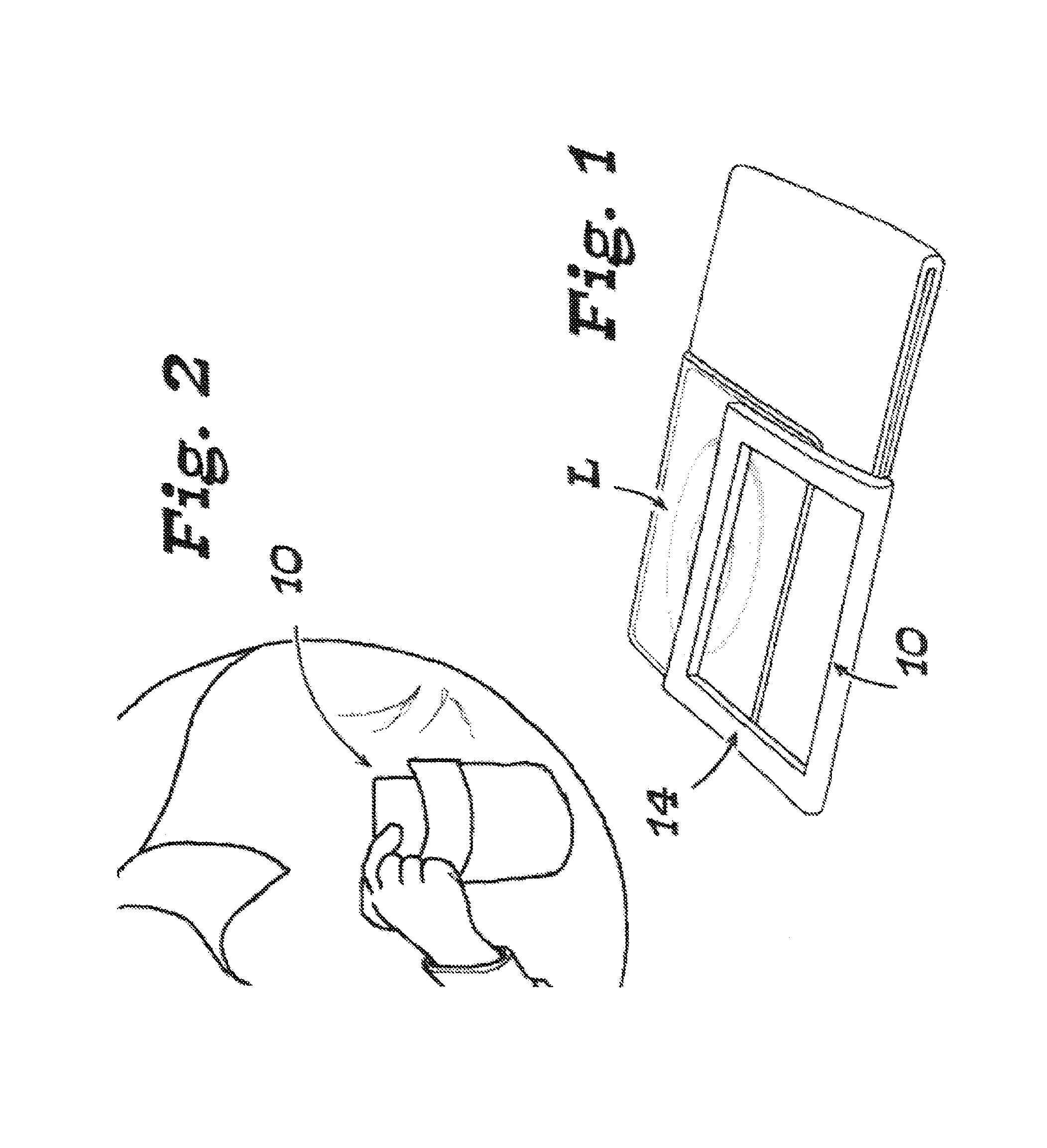
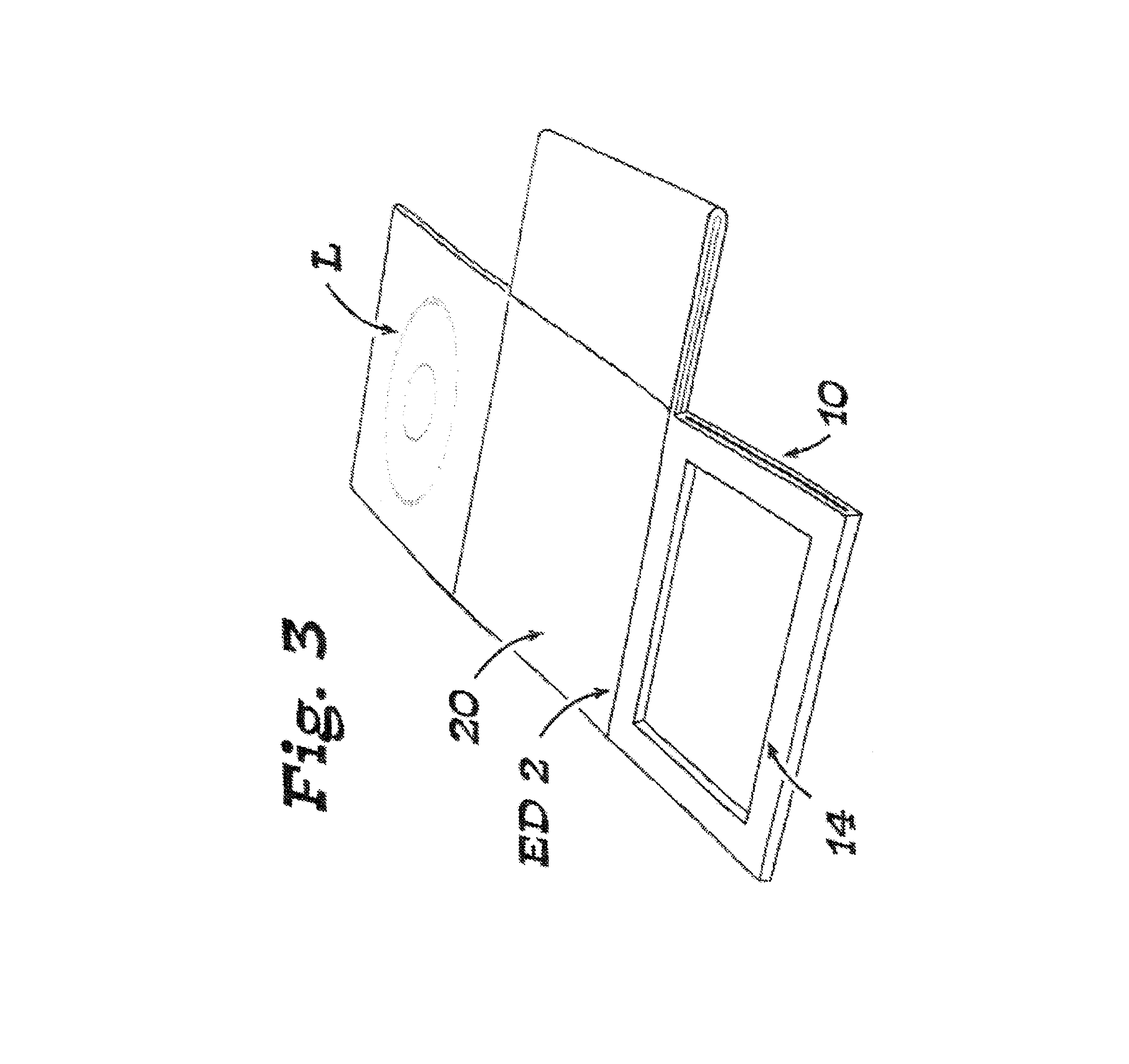
The patent describes a device that can be attached to a camera screen and used to take pictures. The device has a compact, closed condition that fits into a pocket, and can be unfolded and used to take pictures on the go. The device is stable and easy to hold and track subjects with, making it a convenient and efficient tool for photography.

Problems solved by technology

My device and method are, however, susceptible to modifications and alternate constructions from the illustrative embodiments discussed above which are fully equivalent.

Method used


Image

  • Eye level viewfinder and three dimensional virtual reality viewing device and method
  • Eye level viewfinder and three dimensional virtual reality viewing device and method
  • Eye level viewfinder and three dimensional virtual reality viewing device and method

Examples


Embodiment Construction

.” The claims that follow define my glare blocking viewfinder device and method of taking a picture using my device, distinguishing them from the prior art; however, without limiting the scope of my glare blocking device and method as expressed by these claims, in general terms, some, but not necessarily all, of their features are:

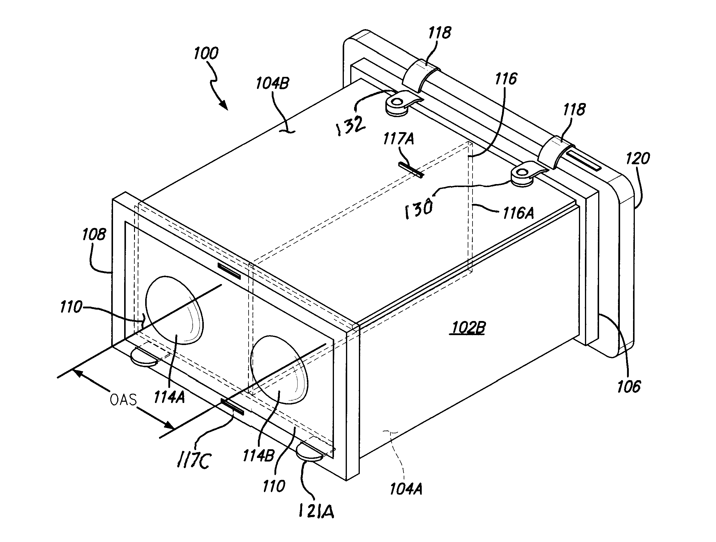
[0010]One, my glare blocking viewfinder device includes a shadow box having opposed first and second open ends and a predetermined depth dimension. There is a lens at the first end and an attachment mechanism at the second end. The depth dimension of the shadow box is substantially equal to the focal length of the lens.

[0011]Two, the lens is mounted to move between positions that cover and uncover the first end, which functions as the viewing end. The lens may be detachable or permanently affixed. In one embodiment, a substantially flat, thin, planar, rectangular lens is used that is mounted by a hinge to the shadow box to move through an arc of substantia...


PUM


Abstract

A device that allows viewing of 3D and virtual reality that is displayed on a portable device such as a cell phone for example an iPhone or any such type known as a smartphone. The device has vertical and horizontal panels that are hinged together to fold flat and to unfold into a box shape. One end is an attachment frame that allows attaching of the display source device so that its screen can be seen through the open box from the other end. On the other end is a lens frame on which are a pair of spaced apart lens for viewing separately of each eye thereby allowing 3 D viewing. The device can be equipped with a sterol separator wall to prevent vision confusion. All the parts are hinged together so as to allow the entire device to fold into a generally flattened package.

Description

RELATED PATENT APPLICATIONS & INCORPORATION BY REFERENCE[0001]This utility application is a continuation-in-part of application Ser. No. 13 / 844,308 filed on Mar. 15, 2013 which is a continuation-in-part of application Ser. No. 12 / 814,436 filed on Jun. 11, 2010 which claims the benefit under 35 U.S.C. 119(e) of U.S. Provisional Patent Application No. 61 / 218,334 filed Jun. 18, 2010 all of which are incorporated herein by reference and made a part of this application and from which priority is claimed.BACKGROUND[0002]Small, lightweight, commercially available hand-held cameras have side mounted, wing-like flat panel imagers or LCD monitor screens that are moveably attached to the camera body to pivot between a stored position and an outwardly extended position from the camera body during use. Images of the object being photographed are displayed on the monitor screen. These cameras do not have built-in eye level viewfinders, so the user normally holds the screen away from his or her ey...

Claims


Application Information

Patent Timeline
Patent Type & Authority Patents(United States)
IPC IPC(8): G02B27/22G02B27/02
CPCH04N5/23293G02B27/2257G02B27/027G02B27/028G03B11/046G02B30/37
Inventor MARGOLIN, GEORGE
Owner MARGOLIN GEORGE
Learn More