Balance spring stud-holder
a technology of balance spring and stud, which is applied in the direction of instruments, regulation mechanisms, and operations to be performed with these various elements, affecting the operation of balance springs, and affecting the operation of balance springs. it can solve the problems of affecting the operation of balance springs, and the clamping screw of balance springs or the balance spring stud holders can not be removed, so as to achieve the effect of simplifying the assembly or disassembling
- Summary
- Abstract
- Description
- Claims
- Application Information
AI Technical Summary
Benefits of technology
Problems solved by technology
Method used
Image

Examples
first embodiment
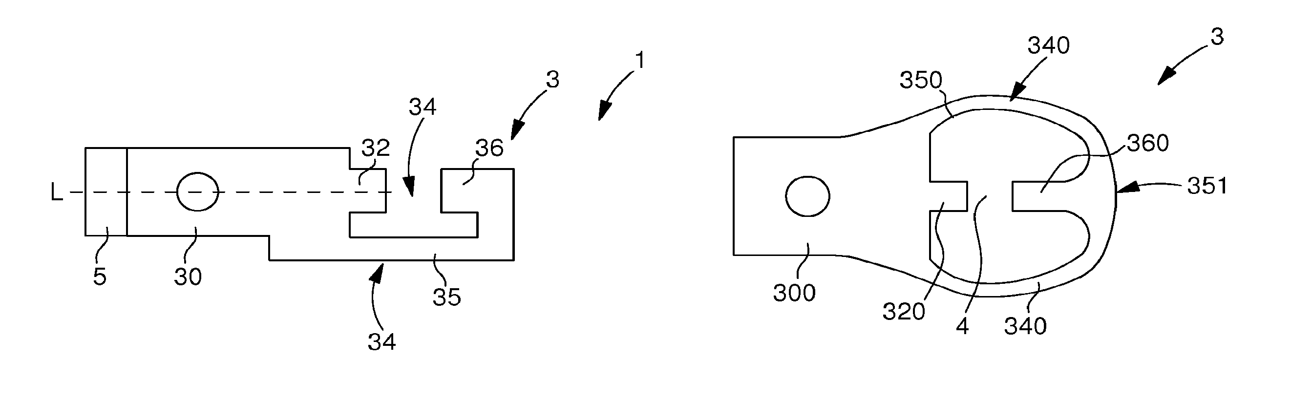
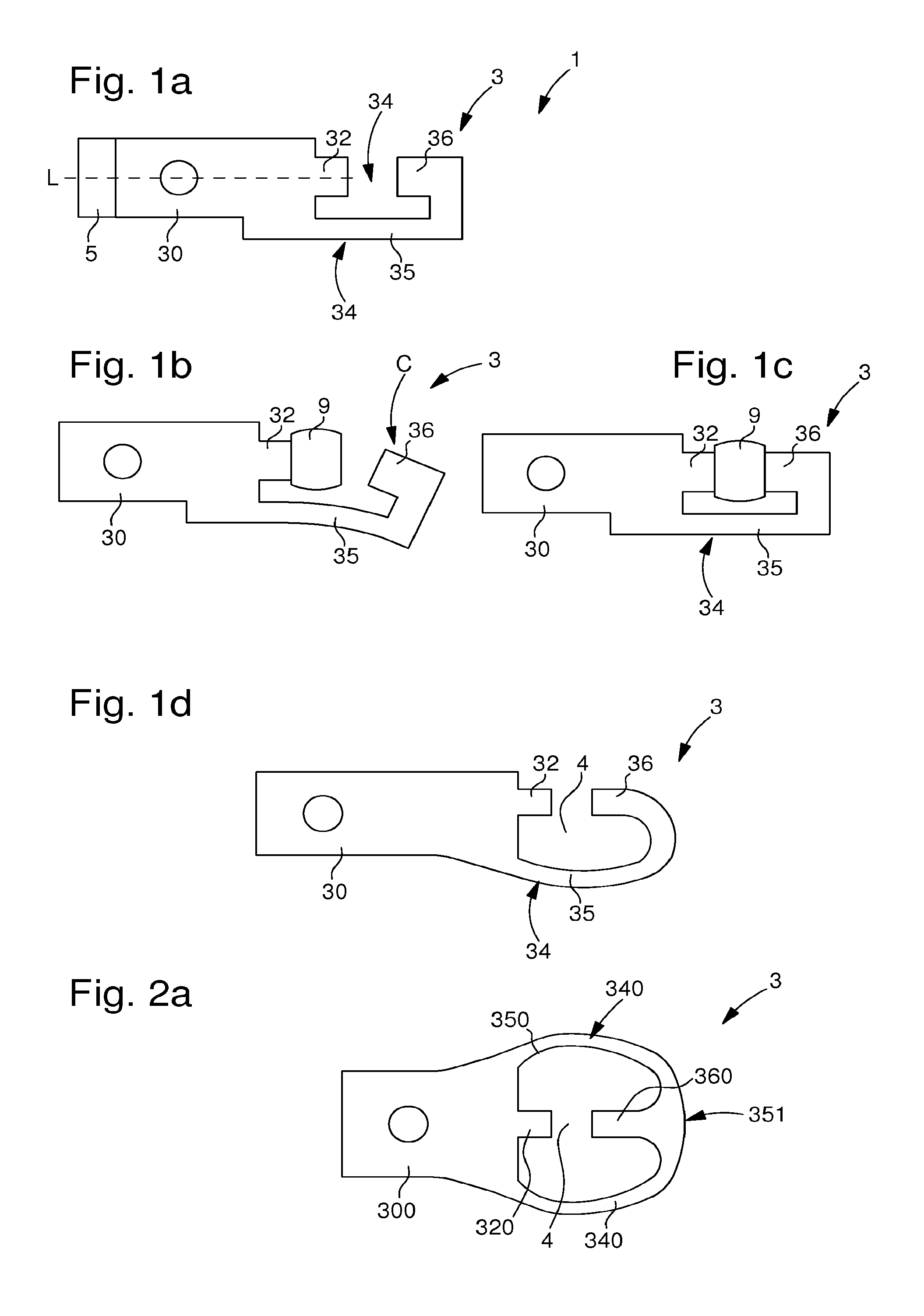
[0036]FIGS. 1a to 1d show schematic views of an assembly 1 for holding or supporting a balance spring stud according to a This holding assembly 1 includes a stud-holder 3 arranged to be attached to the balance-cock 5 by means of attachment 7. The holding assembly also includes a balance spring stud 9 attached to one coil of the balance spring.
[0037]Stud-holder 3 includes a base 30 having a longitudinal axis. Base 30 may have any shape. From base 30 there extends a first stop member 32. This first stop member takes the form of a protruding portion of base 30.
[0038]Advantageously according to the invention, stud-holder 3 also includes elastic means 30 for provided for the attachment of stud 9 to the stud-holder.
[0039]In the first embodiment seen in FIG. 1a, the elastic means include an arm 35. This arm 35 extends from base 30 in a similar direction to that of first stop member 32, i.e. in a similar direction to that of the longitudinal axis. This arm 35 has a rectilinear shape ending...
second embodiment
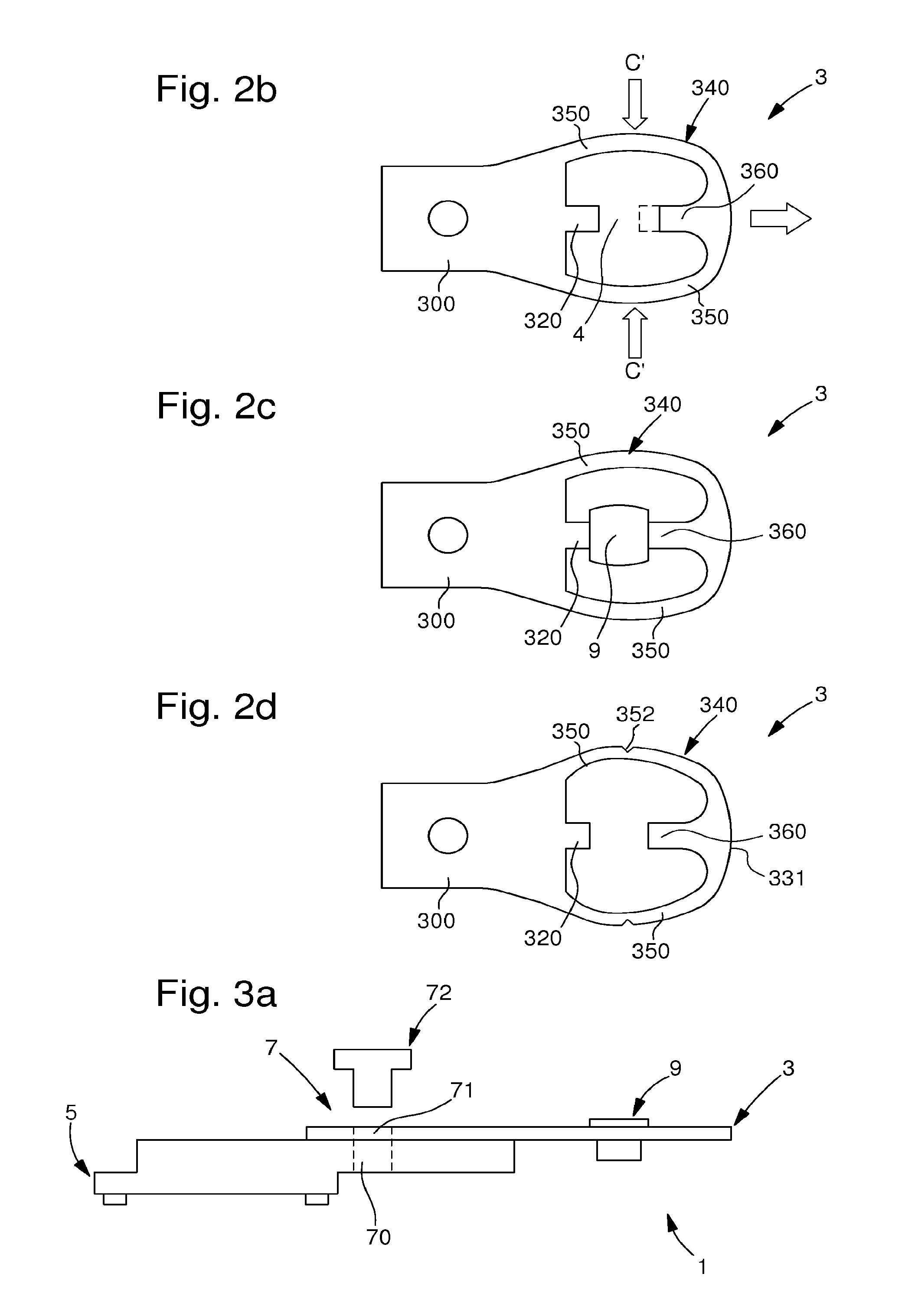
[0046]In a second embodiment seen in FIG. 2a, elastic means 340 include two elastic arms 350. Each elastic arm 350 includes a first end and a second end. These arms 350 extend from base 300, via the first end, in a similar direction to that of first stop member 320, i.e. in a similar direction to that of the longitudinal axis.
[0047]In this second embodiment, the two elastic arms 350 are joined at their second end. At this joining point 351, second stop member 360 is arranged to face first stop member 320.
[0048]According to the invention, the two elastic arms 350 cleverly each have a curvature. This curvature is preferably convex. This convex shape of elastic arms 350 permits simplified assembly / disassembly of stud 9. Indeed, in order to assemble / disassemble the stud, a stress C′ is simultaneously applied to the two elastic arms 350. This stress C′ applied to each elastic arm 350 causes a deformation of arms 350. This deformation is intended to bring them closer together as seen in F...
third embodiment
[0074]In a third embodiment, stud-holder 3 and balance-cock 5 are made in one-piece, i.e. they form the same single component. In this regard, balance-cock 5 acts as base 3, which includes the first stop member and from which extend the elastic arm or arms 35, 350 forming elastic means 34, 340.
[0075]This third embodiment eliminates the need for means 7 for attaching stud-holder 3 to balance-cock 5. There is consequently a risk of improper positioning during the assembly of the stud-holder to the balance-cock.
[0076]Further, this third embodiment reduces costs since there is only one part instead of two and the method contains one less step.
[0077]It will be clear that various alterations and / or improvements and / or combinations evident to those skilled in the art may be made to the various embodiments of the invention set out above without departing from the scope of the invention defined by the annexed claims.
[0078]For example, the first stop member may be configured to act as a stop ...
PUM
 Abstract
Description
Claims
Application Information