Pull cord for controlling a window covering

a technology for controlling a window covering and a pull cord, which is applied in the direction of door/window protective devices, instruments, gearing, etc., can solve the problems of prohibitively expensive replacement of window blinds with automated versions of the same, expensive replacement of these devices, and difficult decision for home or business owners to install smart devices, etc., to achieve the effect of reducing gearbox nois

Active Publication Date: 2016-10-18
HALL LABS LLC
View PDF17 Cites 15 Cited by
  • Summary
  • Abstract
  • Description
  • Claims
  • Application Information

AI Technical Summary

Problems solved by technology

Home automation may be as simple as automating a few devices in a relatively small home or space, or as complicated as automating an entire residence or building comprising hundreds or even thousands of smart devices.
Nevertheless, outfitting a home with smart devices can be a difficult decision for a home or business owner.
Replacing these devices can be expensive and / or wasteful.
Replacing the window blinds with automated versions of the same can be prohibitively expensive in addition to requiring significant amounts of labor.
Retrofitting the window blinds can also be problematic in that multiple different designs and sizes of window blinds may exist, and retrofit solutions may be limited in terms of the designs and sizes they can work with.
Many offerings in terms of automated window blinds or window coverings may also fail to capitalize on their special placement within a home or building, namely on or near windows or other openings.

Method used


Image

  • Pull cord for controlling a window covering
  • Pull cord for controlling a window covering
  • Pull cord for controlling a window covering

Examples


Embodiment Construction

[0065]It will be readily understood that the components of the present invention, as generally described and illustrated in the Figures herein, may be arranged and designed in a wide variety of different configurations. Thus, the following more detailed description of the embodiments of the invention, as represented in the Figures, is not intended to limit the scope of the invention, as claimed, but is merely representative of certain examples of presently contemplated embodiments in accordance with the invention. The presently described embodiments will be best understood by reference to the drawings, wherein like parts are designated by like numerals throughout.

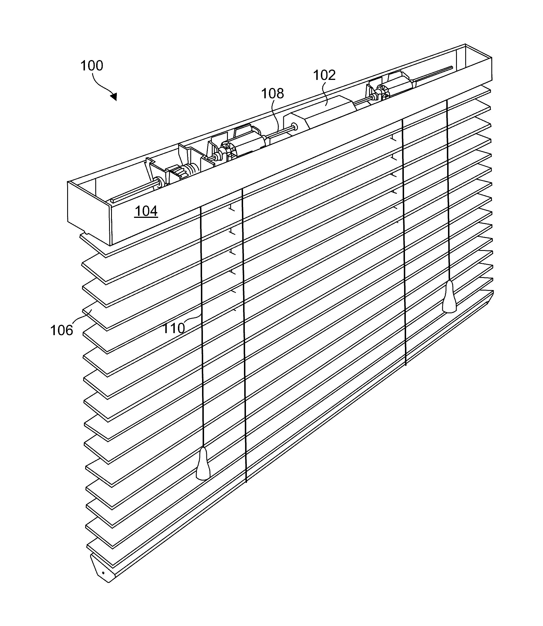
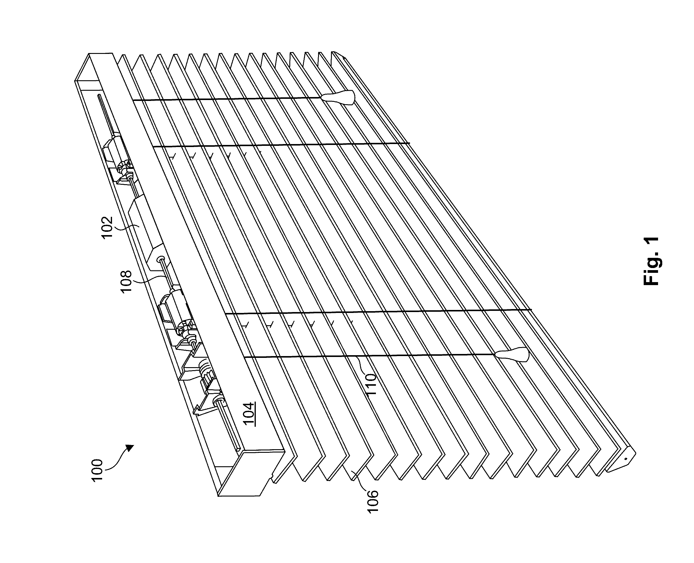
[0066]Referring to FIG. 1, one example of a window covering 100, in this example a conventional window blind 100, is illustrated. As shown, the window blind 100 includes a headrail 104, containing various components, and slats 106. In the illustrated embodiment, the window blind 100 is retrofitted with a motorized gearbox a...


PUM

PropertyMeasurementUnit
lengthaaaaaaaaaa
lengthaaaaaaaaaa
strengthaaaaaaaaaa

Abstract

An apparatus in accordance with the invention includes a window covering actuation mechanism and a gearbox assembly configured to electromechanically operate the window covering actuation mechanism. A pull cord is configured to receive “cord gestures” from a user. These “cord gestures” may include one or more of pull sequences, pull durations, numbers of pulls, durations between pulls, and strength of pulls. In certain embodiments, “cord gestures” may also be defined by pull direction. A controller receives the cord gestures and translates the cord gestures into commands for controlling the gearbox assembly. A corresponding method is also disclosed herein.

Description

RELATED APPLICATIONS[0001]This application claims priority to U.S. Provisional Patent No. 61 / 977,008 filed on Apr. 8, 2014 and entitled “Intelligent Window Coverings”; U.S. Provisional Patent No. 62 / 005,140 filed on May 30, 2014 and entitled “Universal Motorized Blind Tilt Mechanism”; and U.S. Provisional Patent No. 62 / 051,048 filed on Sep. 16, 2014 and entitled “Cable Pull Switch with Power and Data Pass-Through Capability”. This application is also a continuation of U.S. patent application Ser. No. 14 / 682,077 filed on Apr. 8, 2015 entitled “Motorized Gearbox Assembly with Through-Channel Design;” and U.S. patent application Ser. No. 14 / 682,085 filed on Apr. 8, 2015 entitled “Headrail Bracket for Installing a Motorized Gearbox Assembly in a Window Covering.”BACKGROUNDField of the Invention[0002]This invention relates to apparatus and methods for automating window blinds and other windows coverings.BACKGROUND OF THE INVENTION[0003]Home automation, also known as home monitoring, home...

Claims


Application Information

Patent Timeline
Patent Type & Authority Patents(United States)
IPC IPC(8): E06B9/32F24J2/40E06B9/308E06B9/326E06B9/38E06B9/68E06B9/42E06B9/74E06B9/72E06B9/34E06B9/303E06B9/266E06B9/322F16H57/023E06B9/307
CPCE06B9/307E06B9/266E06B9/303E06B9/308E06B9/32E06B9/322E06B9/326E06B9/34E06B9/38E06B9/42E06B9/68E06B9/72E06B9/74F16H57/023F24J2/402F24J2/407E06B2009/3222E06B2009/3225E06B2009/6818E06B2009/6827Y10T29/49817Y10T29/49959Y10T74/2186E06B2009/2476E06B2009/285F16H57/02F16H57/021F16H57/028F16H2057/02034F16H2057/02039G08C17/02H01H17/08Y02A30/24Y02B10/20Y02B80/00Y02E10/40F16H1/20F24S50/40F24S50/80
Inventor HALL, DAVID R.CARLSON, AUSTIN BENJAMINCOOK, CLINT JREES, KEVIN DEANHYER, DAVIDO LOYALMILES, JEROME LEEBRIMHALL, EMILY
Owner HALL LABS LLC
Why Eureka
Try Eureka