Illuminated windshield system

a technology of illuminated glass and windshield, which is applied in the direction of glass construction, semiconductor devices for light sources, lighting and heating apparatus, etc., can solve the problems of disrupting the internal reflectivity of the windshield,

Active Publication Date: 2017-01-03
N A TAYLOR CO INC
View PDF11 Cites 6 Cited by
  • Summary
  • Abstract
  • Description
  • Claims
  • Application Information

AI Technical Summary

Problems solved by technology

The windshield may include a disruption that disrupts internal reflectivity of the windshield.

Method used


Image

  • Illuminated windshield system
  • Illuminated windshield system
  • Illuminated windshield system

Examples


Embodiment Construction

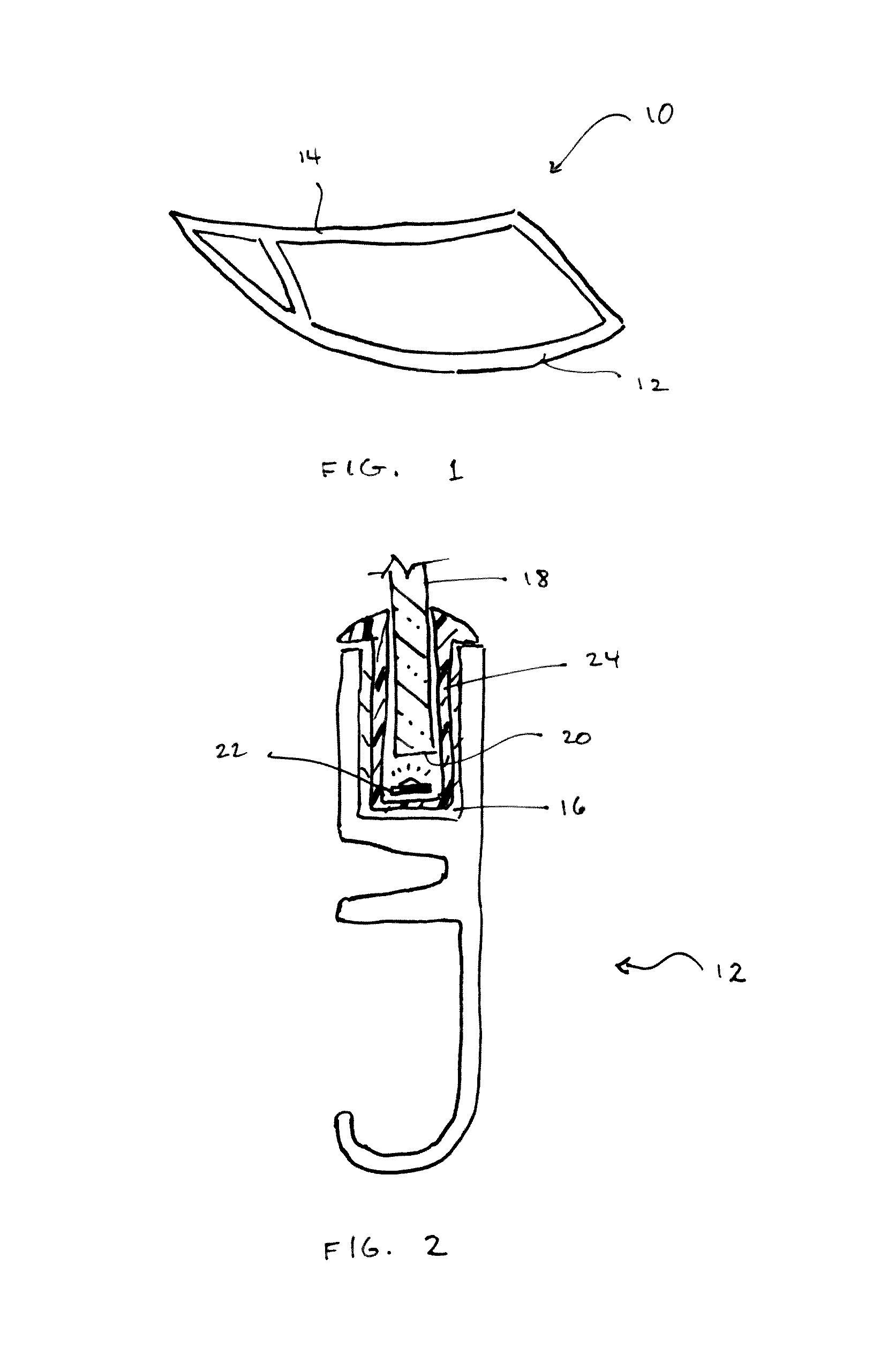
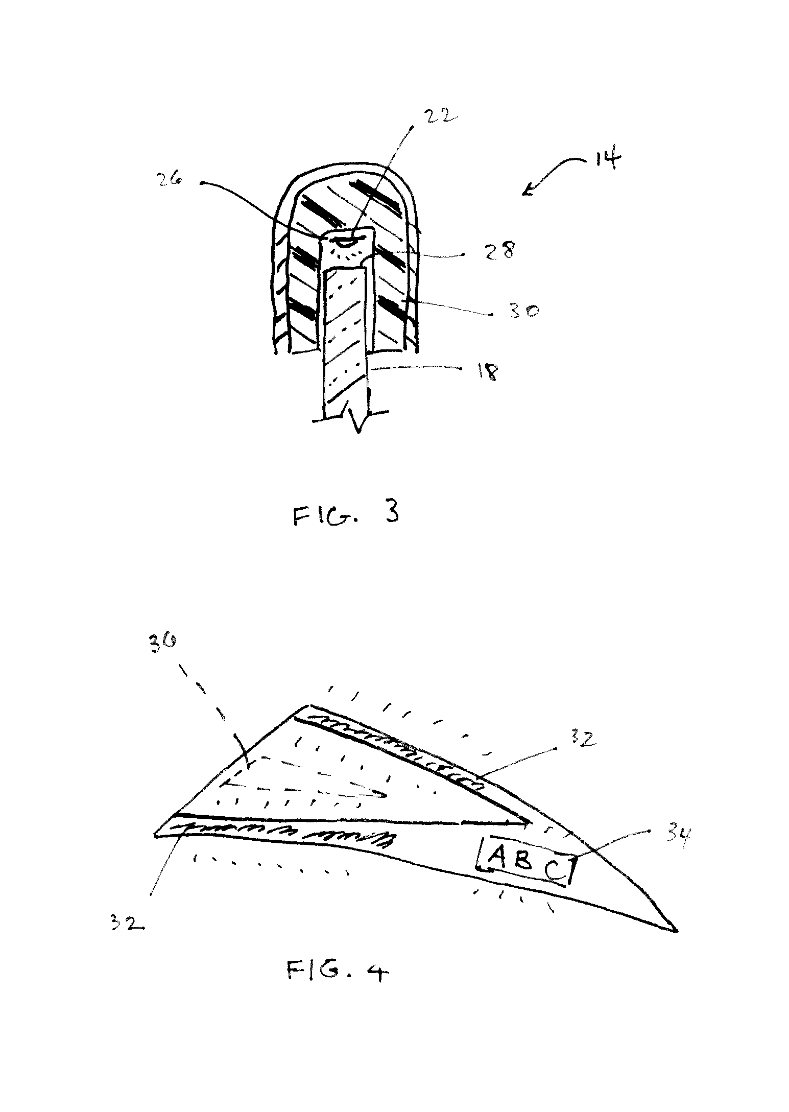
[0016]FIG. 1 is a perspective view of a boat windshield 10 as an exemplary application for the illuminated windshield system of the preferred embodiments. As noted, the use of the term “windshield” in the present application is intended to encompass any glass panel to which the components of the system can be attached. Other exemplary applications may include glass doors, hatches and roof systems.

[0017]Generally, a boat windshield 10 may include a bottom trim member 12 that is secured to a boat hull or the like and possibly also a top trim member 14. Any suitable bottom or top trim members may be used with the system described herein, and the invention is not intended to be limited to any particular trim design. Exemplary trim members are described in U.S. Pat. Nos. 6,453,841, 6,895,885, D505,909, 7,565,878 and 7,591,231, the disclosures of which are hereby incorporated by reference.

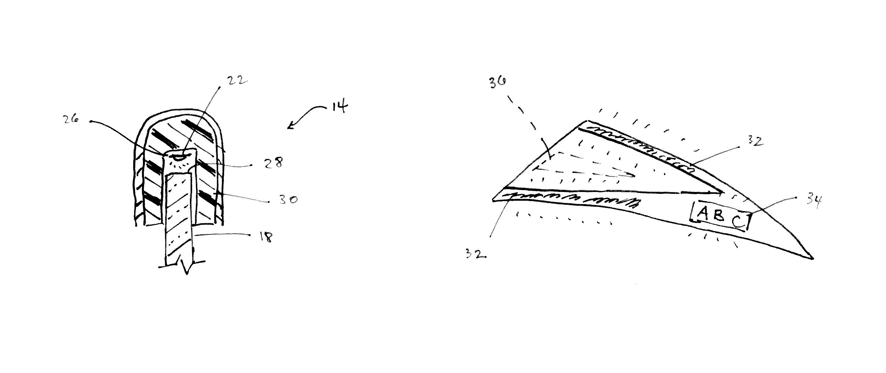
[0018]FIG. 2 is a sectional view of the illuminated windshield system with the bottom trim member 12....


PUM


Abstract

An illuminated windshield system includes a trim member with a channel for receiving a windshield, and a windshield mounted in the channel and having an edge. A light source is interposed between the channel of the trim member and the edge of the windshield. The light source is disposed facing the edge of the windshield.

Description

CROSS-REFERENCES TO RELATED APPLICATIONS[0001]This application claims the benefit of U.S. Provisional Patent Application No. 61 / 970,474, filed Mar. 26, 2014, the entire content of which is herein incorporated by reference.STATEMENT REGARDING FEDERALLY SPONSORED RESEARCH OR DEVELOPMENT[0002](NOT APPLICABLE)BACKGROUND AND SUMMARY OF THE INVENTION[0003]The invention relates to illuminated glass systems and, more particularly, to an illuminated windshield system cooperable with a windshield secured in a trim member.[0004]The illuminated windshield system according to preferred embodiments includes a light source that is placed on and follows along the edge of a glass component. The system is applicable to any glass type, for example, glass doors, hatches, windshields, and roof systems in industries such as marine, agriculture, power sport, and others. Reference to “windshield” in the present application is intended to refer generically to any glass panel to which the system may be appli...

Claims


Application Information

Patent Timeline
Patent Type & Authority Patents(United States)
IPC IPC(8): B60Q1/00B60J1/00B60Q3/02B60Q1/26B63B45/04B63B19/02F21V7/00F21V1/00B60J1/08F21W107/20
CPCF21V7/0091B60J1/004B60J1/08B60Q1/268B60Q3/0213B63B19/02B63B45/04F21S4/28F21V2200/20F21W2101/04F21Y2103/10F21Y2115/10B60Q3/208F21W2107/20
Inventor TRAJLINEK, MICHAELOAKES, PHILIP A.
Owner N A TAYLOR CO INC
Why Eureka
Try Eureka