Porous matrix sound suppressor

a sound suppressor and porous matrix technology, applied in the direction of weapons, weapon components, etc., can solve the problems of increasing the blowback, unsatisfactory or inconvenient for some users, adding significant weight to the firearm, etc., and achieve the effect of increasing the surface area of the suppressor

Active Publication Date: 2017-01-17
EMPOREUM PLASTICS
View PDF21 Cites 11 Cited by
  • Summary
  • Abstract
  • Description
  • Claims
  • Application Information

AI Technical Summary

Benefits of technology

[0006]This disclosure is directed to a suppression device that employs a porous micro-channel diffusion matrix surrounding the outer surface of a hollow core tube, replacing the traditional inner baffling, to diffuse, slow and cool gasses released from the discharge of a firearm; reducing the audible signature. As a bullet passes through the hollow core tube, propellant gasses are released though the vents of the hollow core tube and into the porous micro-channel diffusion matrix where the gasses are cooled, slowed, and diffused into the atmosphere. The porous micro-channel diffusion matrix is interposed between containment caps. At the distal end (with respect to the firearm's muzzle) is a containment cap and at the proximal end is a muzzle connection cap that connects the device to the end of the firearm barrel. The suppression device disclosed effectively reduces the audible signature associated with the discharge of a firearm as well as reducing the Hash associated with the release of combustion gasses out of the muzzle.
[0007]The advantages of the present invention are that it provides for a suppressor with a porous micro-channel diffusion matrix that:(a) reduces the muzzle flash and the audible sound associated with the discharge of a firearm;
[0008](b) exponentially increases the surface area of the suppressor when compared to traditional inner baffling designs, allowing combustion gasses to diffuse and exit the device across the entire outer surface of the suppressor rather than only through a single aperture located at the distal end;(c) does not substantially change the point-of-impact of the bullet on its target;(d) does not substantially increase the overall weight of the firearm;(e) does not substantially increase blowback;(f) does not substantially heat the barrel resulting in the mirage effect, a decreased barrel lifetime and in decreased efficiency of the suppressor; and(g) has a lower cost of manufacturing when compared to traditional suppressors.

Problems solved by technology

Traditional suppressor designs have drawbacks that make them undesirable or inconvenient for some users.
Drawbacks of these traditional suppressors may include but are not limited to: altering the point of the bullet's impact on the target; adding significant weight to the firearm; increasing the blow back; having increased difficulties and increased costs associated with manufacturing intricate designs; changing the recoil of the firearm; increasing the barrel temperature of the firearm which gives the user a perceived mirage effect and decreases the effectiveness of suppressor, and difficulty in cleaning.
(a) reduces the muzzle flash and the audible sound associated with the discharge of a firearm;
(b) exponentially increases the surface area of the suppressor when compared to traditional inner baffling designs, allowing combustion gasses to diffuse and exit the device across the entire outer surface of the suppressor rather than only through a single aperture located at the distal end;
(c) does not substantially change the point-of-impact of the bullet on its target;
(d) does not substantially increase the overall weight of the firearm;
(e) does not substantially increase blowback;
(f) does not substantially heat the barrel resulting in the mirage effect, a decreased barrel lifetime and in decreased efficiency of the suppressor; and

Method used


Image

  • Porous matrix sound suppressor
  • Porous matrix sound suppressor
  • Porous matrix sound suppressor

Examples


Embodiment Construction

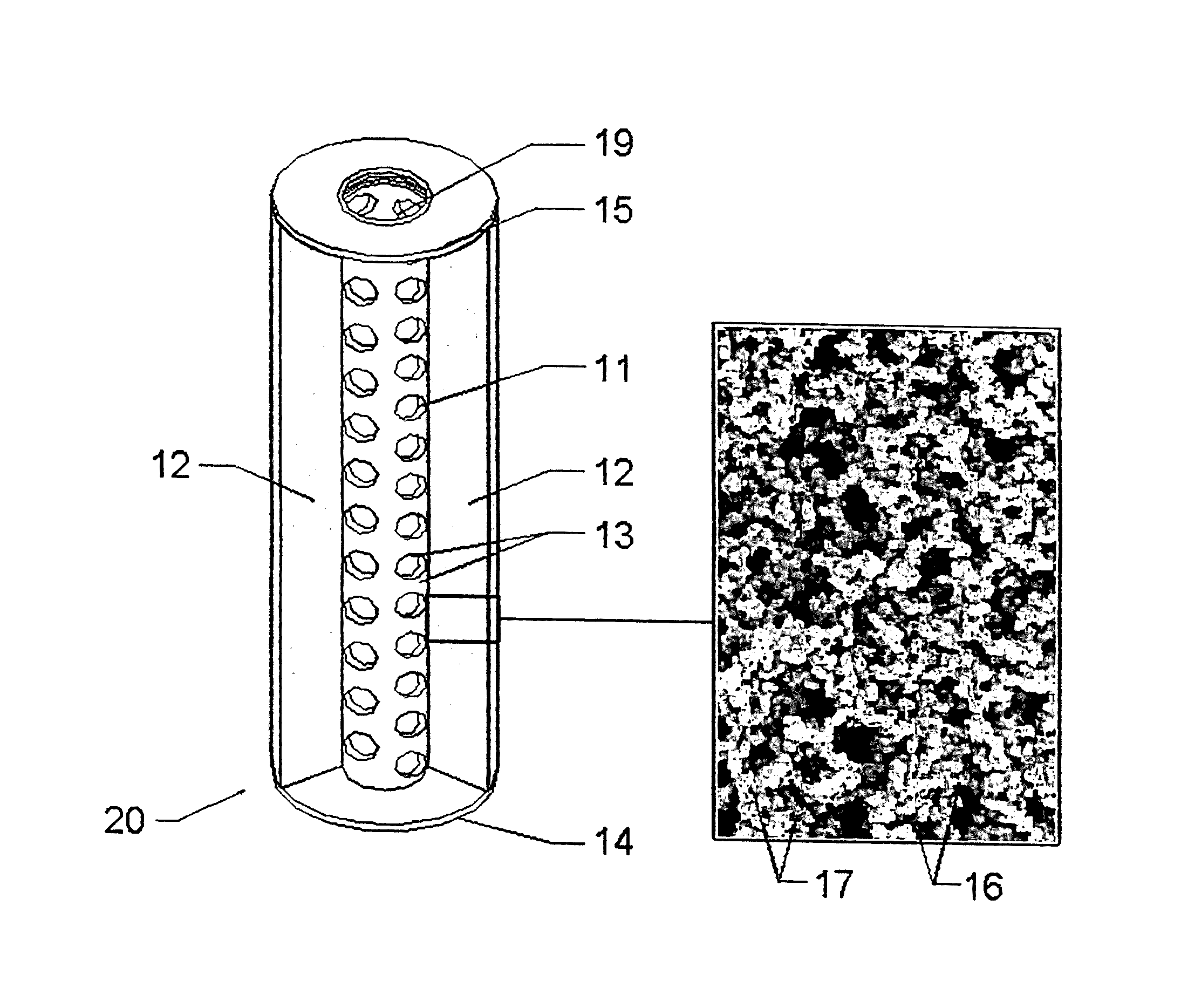
[0019]Firearm suppressors are used to reduce the muzzle flash and the audible sound associated with the discharge of a firearm. However traditional suppressors also have negative effects. Most suppressors change the point of impact; add significant weight to the firearm; increase the blow back; change the recoil; increase the barrel temperature resulting in the perceived mirage effect and decreasing the effectiveness and shorted barrel lifetime, and are difficult to clean. Traditional suppressors also have complex designs such as inner baffling. The intricate designs of traditional suppressors increase their cost of manufacturing. The embodiments disclosed here minimize these negative effects.

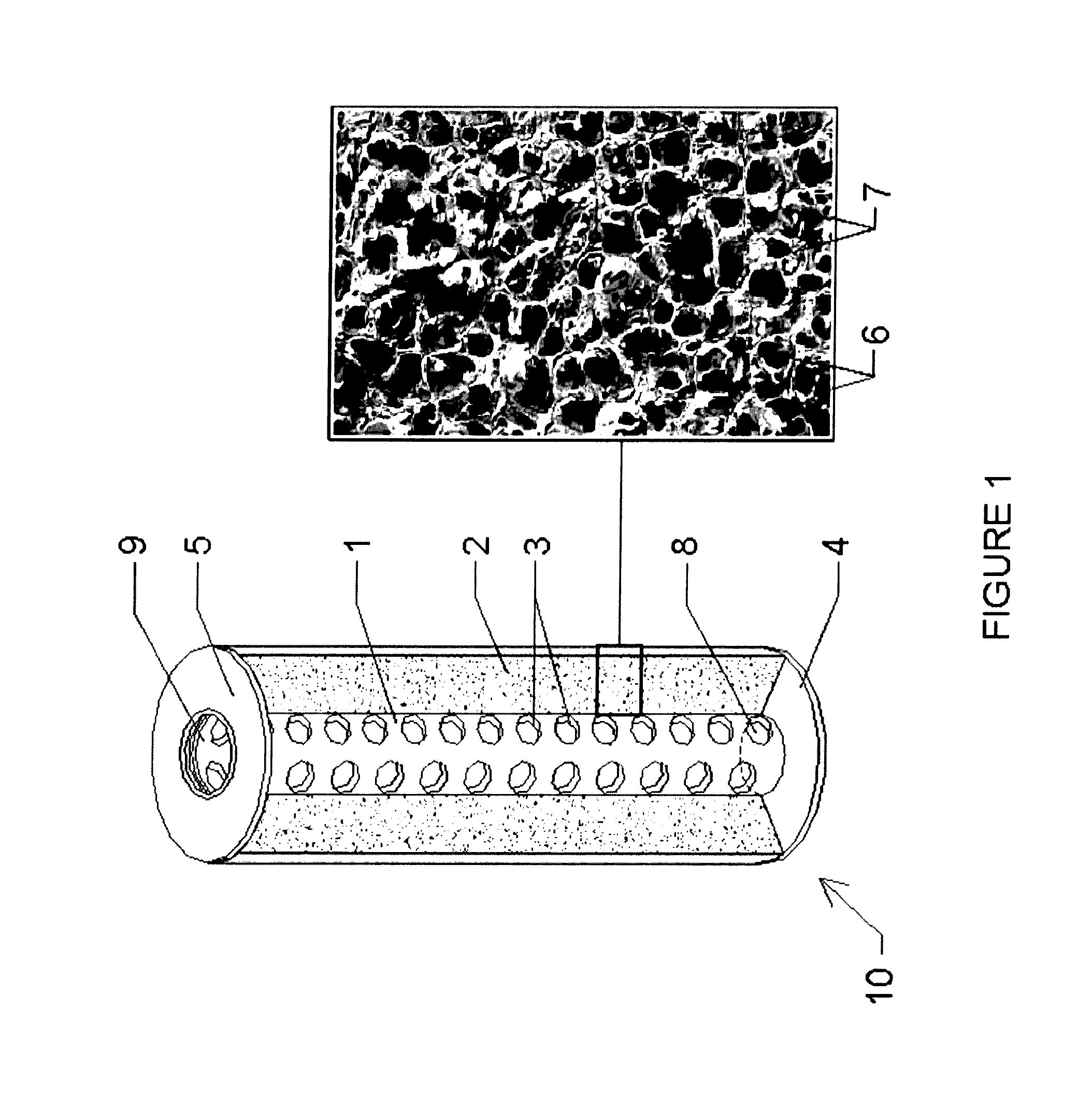
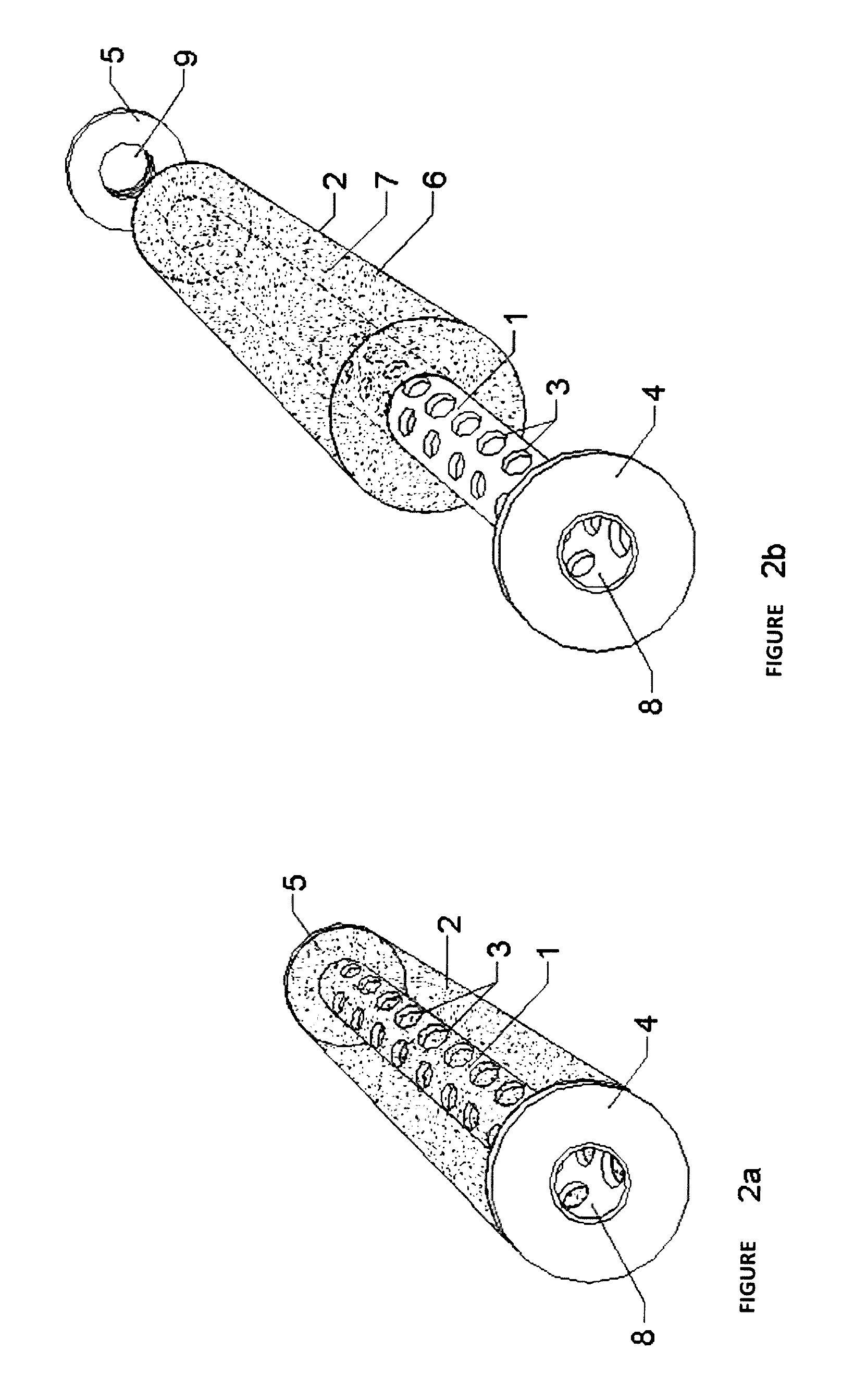
[0020]FIG. 1 shows suppressor device 10 comprised of hollow core tube 1 within porous micro-channel diffusion matrix 2. Hollow core tube 1 is comprised of circular vents 3. In some embodiments the ends of the hollow core tube may threaded. Hollow core tube 1 is connected by the use of threads o...


PUM


Abstract

Disclosed is a sound-suppressing device that employs a porous micro-channel diffusion matrix surrounding a hollow core tube that acts to exponentially increase the surface area of the suppressor and allow combustion gasses to diffuse and exit the suppressor across the entire outer surface of the suppressor.

Description

[0001]This application claims priority to provisional application No. 62 / 009,732 filed on Jun. 9, 2014, entitled Porous Matrix Sound Suppressor.FIELD OF INVENTION[0002]The invention pertains to a sound-suppressing device for reducing the magnitude of perceived sound that occurs during the discharge of a firearm. Specifically, it pertains to a device that employs a porous micro-channel, diffusion matrix surrounding a core tube, interposed between a distal containment cap and a proximal muzzle connection cap.BACKGROUND OF INVENTION[0003]Sound generation occurs when discharging a firearm. The sound heard is due to the following sources: the ignition of the cartridge; the discharge of propellant gas from the end of the barrel of a firearm, the flight of the bullet, the bullet impacting its target and the mechanical operation of the firearm itself. Multiple technologies can be employed to reduce the perceived sound associated with discharging a firearm. Typically, a suppressor (commonly ...

Claims


Application Information

Patent Timeline
Patent Type & Authority Patents(United States)
IPC IPC(8): F41A21/30
CPCF41A21/30
Inventor LISKEY, BRADLEY LEEPHILLIPS, RYAN STEVENWHITE, DANIEL EARL
Owner EMPOREUM PLASTICS
Why Eureka
Try Eureka