Expandable inter-vertebral cage and method of installing same

a technology of intervertebral cage and extension, which is applied in the field of spine diseases, can solve the problems of increasing the risk of complications and infection, increasing the risk of torsion stress on the hinge elements, and requiring a large incision, so as to reduce the number of potential complications and ensure optimal placement in the intervertebral space

Active Publication Date: 2017-02-07
UNIVERSITY OF TOLEDO
View PDF92 Cites 35 Cited by
  • Summary
  • Abstract
  • Description
  • Claims
  • Application Information

AI Technical Summary

Benefits of technology

[0008]The inter-vertebral cage of this invention can include several interconnected cage sections that act as load bearing structures. Adjacent ones of the cage sections can be connected to one another by hinge elements formed from shape memory alloy materials, which can be in a torsionally stressed condition and such that they stay in place on their own. Alternatively, the hinge elements may be attached to the respective cage sections by a butt weld or other mechanism. The hinge elements may be bent so as to allow for more active wire within the hinge element such that a larger wire or tube may be used to provide higher restoring torque. The shape memory alloy material can withstand higher deformation than standard engineering metals and can also provide a constant force / torque over a wide range of linear / angular deformation. These properties will be utilized in creating a cage which will automatically activate into and hold a desired orientation during and after installation. The cage will be constructed in its desired shape with a small amount of pre-torque in the hinge element. Once assembled, the cage will assume the initial extended shape, causing the hinge elements to be torsionally stressed. The cage will then be placed within an installation device, such as an endoscope, which will hold the deformed shape until the cage is inserted within an inter-vertebral space. In doing this, the actuation of the shape memory / superelastic alloy will close an extended cage into a desired shape, preferably defining an open cavity for the placement of bone graft material. Following the placement of the graft material, a final securing screw can be applied to secure the end sections of the inter-vertebral cage and thereby close same. Also, the cage sections may have pyramidal-shaped protrusions or other features provided on the top and / or bottom surfaces thereof to facilitate proper securing of the cage as a whole to the adjacent vertebral bodies.
[0010]The installation of the inter-vertebral cage of this invention can be accomplished directly by means of a minimally invasive installation technique. Alternatively, a new technique is proposed for implanting this cage using an endoscope. The endoscope method is still minimally invasive in nature, but would allow direct visualization of every stage of the procedure by the surgeon, thereby reducing the number of potential complications. The configuration of the cage can be designed in such a way that it can be inserted by any known minimally invasive technique or by new techniques. The cage of this invention is advantageous over known cages in that it give optimal placement in the inter-vertebral space.

Problems solved by technology

Once assembled, the cage will assume the initial extended shape, causing the hinge elements to be torsionally stressed.
This secondary activation force often necessitates more time and effort during the surgical procedure and, thus, increases the risk of complications and infection.
Other known cages have been designed utilizing shape memory alloy materials, but they similarly usually require a larger incision due to their “closed loop” design.

Method used


Image

  • Expandable inter-vertebral cage and method of installing same
  • Expandable inter-vertebral cage and method of installing same
  • Expandable inter-vertebral cage and method of installing same

Examples


Embodiment Construction

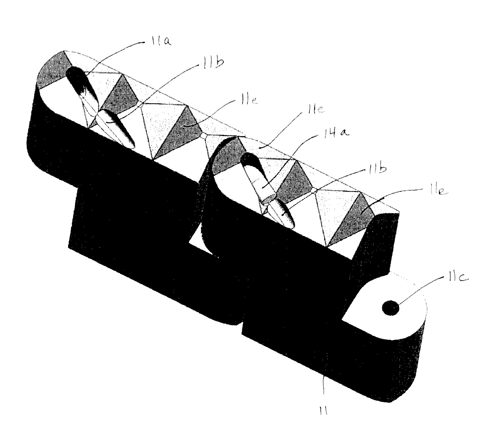
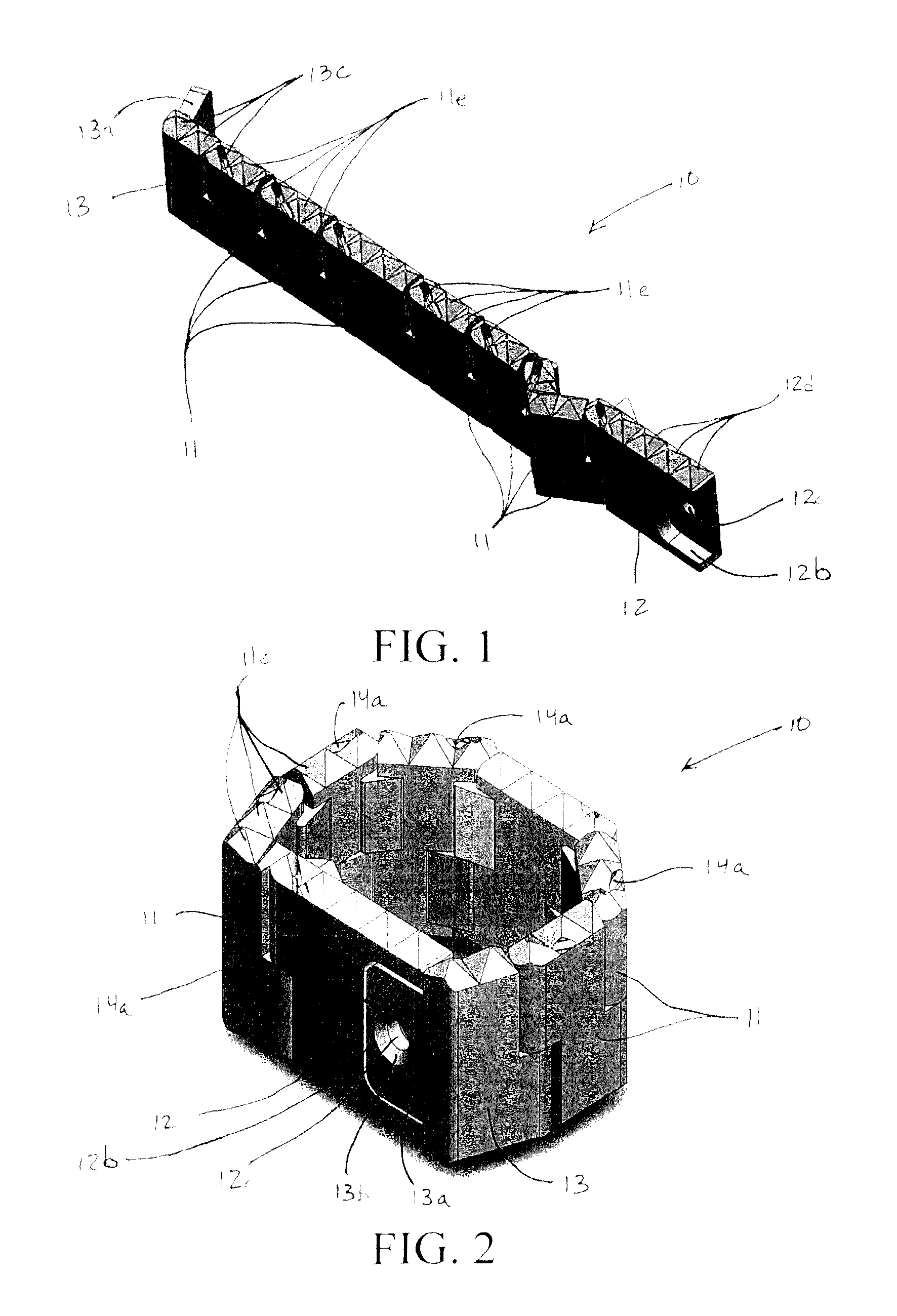
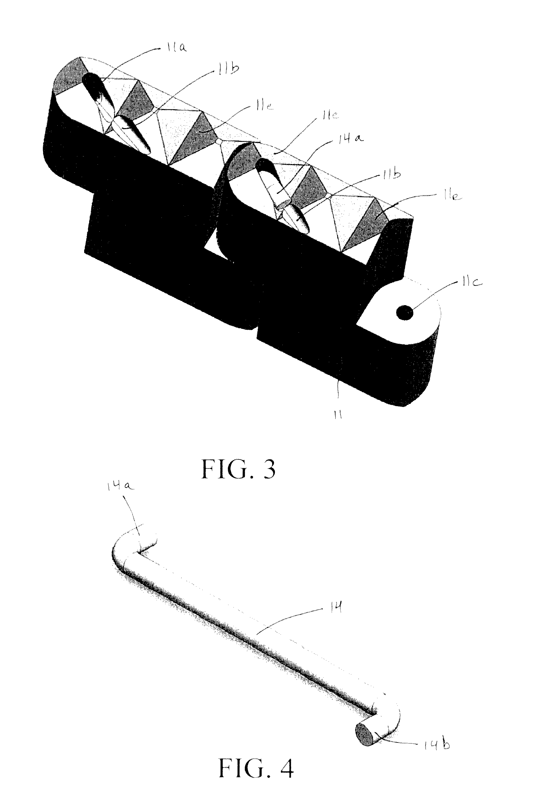
[0038]Referring now to the drawings, there is illustrated in FIGS. 1 through 3 a first embodiment of an inter-vertebral cage, indicated generally at 10, in accordance with this invention. In FIG. 1, the inter-vertebral cage 10 is shown in an initial extended orientation for insertion into a space provided within an inter-vertebral disc that is disposed between two vertebrae of a spine in a manner that will be described in detail below. Following such insertion, the inter-vertebral cage 10 can be moved from this initial extended orientation to a final installed orientation (illustrated in FIG. 2) for use. The manner in which the. cage 10 is moved from the initial extended orientation to the final installed orientation will be explained in detail below.

[0039]The first embodiment of the inter-vertebral cage 10 includes a plurality of individual cage sections 11, a first end section 12, and a second end section 13. In the illustrated embodiment, the inter-vertebral cage 10 includes six ...


PUM

PropertyMeasurementUnit
heightaaaaaaaaaa
angleaaaaaaaaaa
vertical heightaaaaaaaaaa

Abstract

An inter-vertebral cage for use in repairing a damaged inter-vertebral disc includes a plurality of cage sections and a hinge element that connects adjacent ones of the cage sections together for relative movement. The hinge elements automatically urge the cage sections to move from an extended orientation to an installed orientation.

Description

RELATED APPLICATIONS[0001]This is a national stage application filed under 37 C.F.R. §1.371 of international application PCT / US12 / 56297, filed under the authority of the Patent Cooperation Treaty on Sep. 20, 2012, which claims priority to United States Provisional Application Ser. No. 61 / 536,744, filed under 35 U.S.C. §111(b) on Sep. 20, 2011. The entire disclosures of all priority applications are incorporated herein by reference.BACKGROUND OF THE INVENTION[0002]This invention relates in general to the treatment of diseases of the spine using inter-vertebral devices and implantation methods. In particular, this invention relates to an automatically self-expanding inter-vertebral cage that can enter into a cavity through a small opening and automatically acquire any desired form as a result of being either released from an installation tool or from being exposed to environmental conditions, such as temperature, moisture, light, magnetic field, electric field, pressure, etc. (or the ...

Claims


Application Information

Patent Timeline
Patent Type & Authority Patents(United States)
IPC IPC(8): A61F2/44A61F2/46A61B1/018A61F2/28A61F2/30
CPCA61F2/4465A61B1/018A61F2/447A61F2/4611A61F2002/2835A61F2002/30047A61F2002/30092A61F2002/30464A61F2002/30471A61F2002/30472A61F2002/30542A61F2002/30545A61F2002/30556A61F2002/30604A61F2002/30607A61F2002/30609A61F2002/30611A61F2002/30612A61F2002/30616A61F2002/30637A61F2002/30878A61F2002/4415A61F2002/4475A61F2310/00017A61F2310/00023A61F2310/00976A61F2002/30004A61F2002/30433A61F2002/30462A61F2002/3054A61F2002/30593A61F2002/30624
Inventor ELAHINIA, MOHAMMADAGARWAL, ANANDGOEL, VIJAYANDERSON, WALTERCHAPMAN, CORY
Owner UNIVERSITY OF TOLEDO
Why Eureka
Try Eureka