Multifunctional engine brake

a multi-functional, engine technology, applied in the field of machine tools, can solve the problems of reducing or even eliminating the valve motion, reducing the speed of the valve seat, and losing all cam motion, so as to reduce the falling off, and effectively slow down and control the valve seat speed

Active Publication Date: 2019-03-07
SHANGHAI UNIVERSOON AUTOPARTS CO LTD
View PDF0 Cites 1 Cited by
  • Summary
  • Abstract
  • Description
  • Claims
  • Application Information

AI Technical Summary

Benefits of technology

[0028]During the above-mentioned conversion of engine operation modes, if there is a falling off in the inside of the fixed-chain VVDM and the valve is out of control to have a high velocity seating, the seating velocity control mechanism will generate more and more resistance to the rocker arm or valve bridge of the fixed-chain VVDM, make its motion slower and slower, thus effectively slow down and control the valve's seating velocity.
[0029]Another effective way to reduce falling off inside the VVDM is to use an oil control timing (oil feeding and discharging) mechanism. When the no-timing brake oil feed valve is turned on or off to feed or discharge oil randomly, the engine brake will not necessarily to follow to turn on or off immediately, but oil is fed to or discharged from the engine brake through the timing valve system of the oil control timing mechanism at a predetermined timing or phase within the engine cycle (for example, when the rocker arm of the engine rotates within a predetermined angle range), so that the engine brake is timed (at a predetermined time or phase) to turn on or off.
[0030]Compared with the prior art, the present invention has positive and obvious effects. According to the invention, the drive mechanism in the roller shaft moves the roller to different axial positions on the roller shaft to realize the conversion of different engine valve motions. The axial roller drive mechanism is placed in the roller shaft, which has the advantages of simple and compact structure, symmetrical and reliable loading, easy manufacture and assembly, convenient and wide application, etc. Since different cams are independent of each other, their performance can be optimized. For example, the brake cam includes at least one but not more than four brake lobes, resulting in four-stroke braking, two-stroke braking, or one-point five-stroke braking. Transmission of load through mechanical linkage eliminates the defects or failure modes of traditional hydraulic engine brakes such as high oil pressure, high deformation, high leakage and hydraulic jacks caused by hydraulic loading.
[0031]In addition, the present invention supplies oil to the engine brake through the oil control timing mechanism, so that the engine brake is turned on at its correct timing, that is to say, the axial position of the engine roller on the roller shaft can be changed only within a predetermined period of time or phase within the engine cycle, so that the roller will not fall off and cause impact during the transition period from one cam's high position to another cam's low position, and the reliability, stability and durability of the roller shifting mechanism are increased.
[0032]Furthermore, the seating velocity control mechanism of the present invention can also effectively slow down and control the seating velocity of the valve and the internal impact of the axial roller drive mechanism in event that there is a falling off in the inside of the fixed chain VVDM, such as when the roller slides from the high position of one cam to the low position of the other cam.

Problems solved by technology

The structure and control are very complicated, and most of them open the engine valves by hydraulic loading.
By changing the linkage between the cam and the valve, some or all of the cam motion is lost and cannot be transmitted to the valve, resulting in reduction or even complete elimination of the valve motion (cylinder cutout).
Obviously, the valve motion of the lost-motion type will not completely follow the motion of the cam, and the seating velocity of the valve cannot be controlled by the cam.
Unfortunately, the valve seating mechanism for the hydraulic VVDM cannot be applied to the fixed chain VDM.
The above-mentioned fixed chain VVDM by shifting roller still faces two problems.
The first is that the roller drive mechanism drives the roller through the roller fork, which is complicated in structure and installation, and the roller fork will generate asymmetric offset load on the roller.
The other is that since the brake oil feeding (and brake oil discharging) from the brake oil feed valve is random and not timed (the brake oil feed valve is turned on randomly and the oil can flow to the roller driver at any position / phase of the cam), when the roller moves from one axial position to another axial position on the roller shaft, it is possible to create a transition across two cams of different heights (one cam is in the high position and the other cam is in the low position, rather than two cams are at the same height), resulting in falling off and impact of the roller from the high cam to the low cam.

Method used


Image

  • Multifunctional engine brake
  • Multifunctional engine brake
  • Multifunctional engine brake

Examples


embodiment 1

[0049]FIGS. 1, 2 and 3 are used to describe embodiment 1 of the engine valve motion conversion mechanism in the present invention. FIG. 1 is an illustration (side view) of an engine valve drive device in embodiment 1. The valve actuator 200 (the description herein applies to both the intake valve actuator and the exhaust valve actuator) includes cams (such as a conventional ignition cam 230 and an engine brake cam 2302), a roller 235 and a roller shaft 231. In addition to being able to rotate on the roller shaft 231, the roller 235 can also move axially along the roller shaft 231 (FIGS. 2 and 3). This embodiment shows two different cams 230 and 2302 (for example, the conventional ignition cam 230 and the engine brake cam 2302), which have different profile curves (lift and phase), but they are located on the same camshaft, adjacent to each other and have the same or approximately the same inner base circle 225. The valve actuator 200 also includes a rocker arm (also called a roller ...

embodiment 2

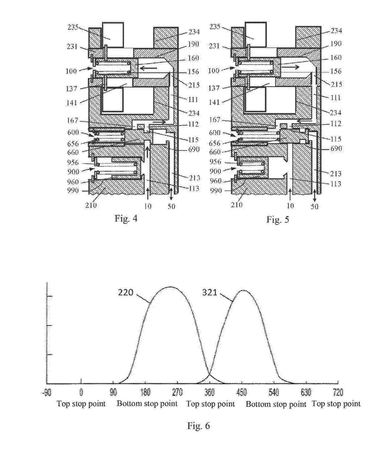
[0056]FIGS. 4 and 5 are used to describe embodiment 2 of the engine valve motion conversion mechanism in the present invention. The main difference between this embodiment and the above embodiment 1 is the oil feeding mode of the axial roller drive mechanism 100. In this embodiment, a directional valve mechanism 600 and an accumulator 900 are added to the rocker arm (roller shaft housing) 210. The directional valve mechanism 600 includes a directional piston 660 and a directional spring 656. One side of the directional piston 660 in the directional piston bore 690 is acted upon by fluid (e.g., oil pressure) and the other side is acted upon by a directional spring 656. The accumulator 900 includes an oil storage piston 960 and an oil storage spring 956. One side of the oil storage piston 960 is acted upon by fluid (e.g., oil pressure) and the other side is acted upon by the oil storage spring 956, so the piston 960 can move between a non-oil storage position (FIG. 4) and a full oil s...

embodiment 3

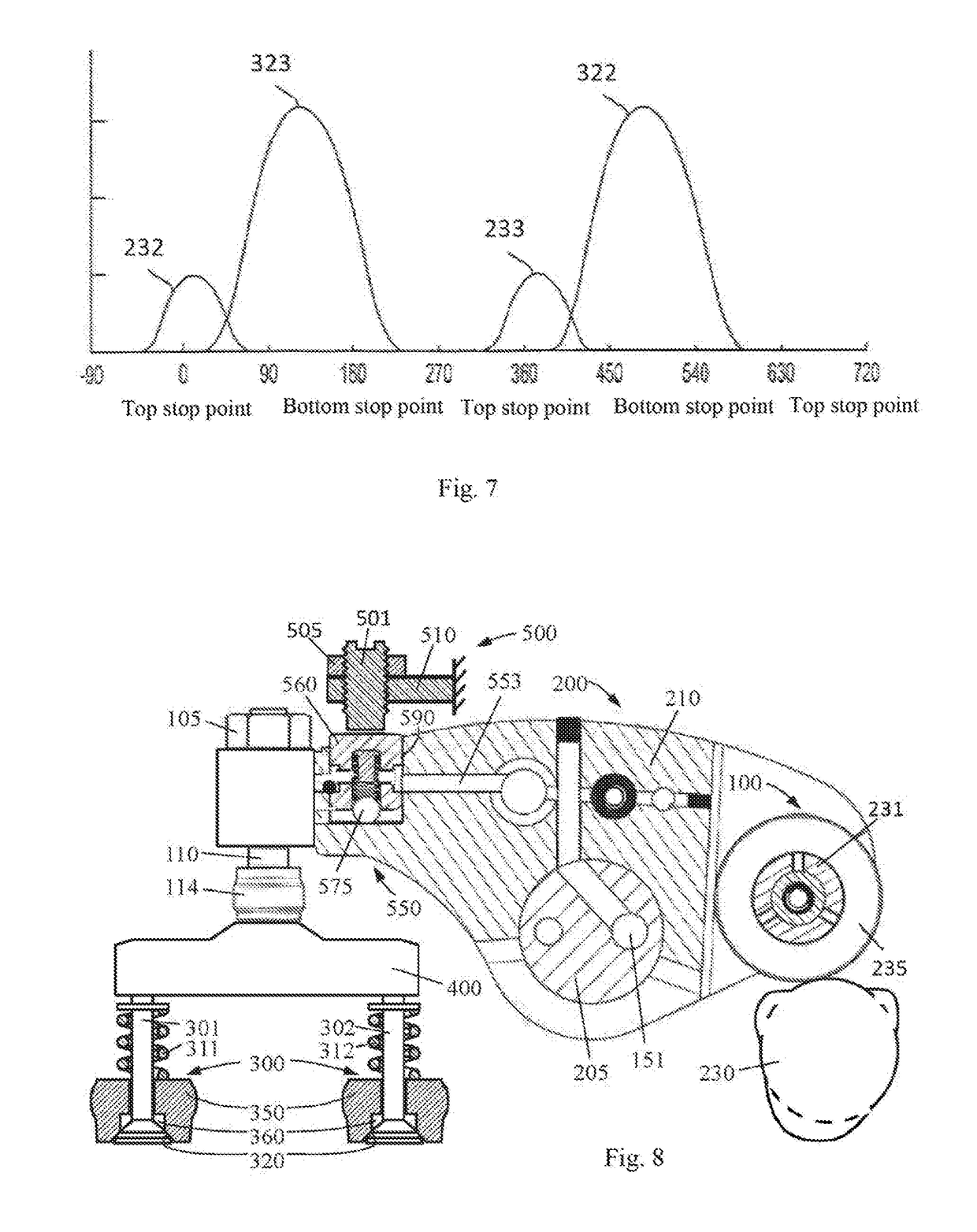
[0059]FIGS. 8, 9 and 10 are used to describe embodiment 3 of the seating velocity control device in the present invention. FIG. 8 is an illustration (side view) of embodiment 3 of the seating velocity control device in the present invention. The rocker arm 210 is connected to the valve bridge 400 on the end close to the valve 300 through a conventional valve lash adjustment mechanism, and the valve bridge 400 acts on both engine valves 300 (301 and 302) (here, a dual valve engine is shown, but the present invention is also applicable to a single valve engine). The two valves 301 and 302 are biased to the valve seat 320 of the engine block 350 by the valve springs 311 and 312, respectively so as to prevent gas from flowing between the engine cylinder and the gas manifold 360. The conventional valve lash adjusting mechanism includes a valve lash adjusting screw 110, a lock nut 105, and an elephant foot pad 114. From the above description, it can be seen that the valve actuator 200 her...


PUM


Abstract

A multifunctional engine brake, comprising an engine valve motion transformation mechanism, a slow seating mechanism (250), and a timing oil control mechanism. By axially moving a roller (235) on a roller shaft (231), the connections between the roller (235) and different cams (230, 2302) are switched, so as to implement the transformation between different engine valve motions. A roller axial driving mechanism (100) is disposed in the roller shaft (231), thereby achieving a simple and compact structure, a symmetrical and reliable force, and easy manufacturing and assembling. The timing oil control mechanism provides timing oil supply or discharge for the engine brake, thereby eliminating the randomness of the opening or closing of a conventional engine brake, avoiding slipping and impact of the roller during roller translation, and improving the reliability and durability of the brake and engine. The slow seating mechanism (250) effectively reduces and controls the seating speed of the valve, thereby eliminating the compact within the mechanism. The brake can be used for different types of variable valve motions, comprising valve motions generating 4-stroke braking, 2-stroke braking, or 1.5-stroke braking.

Description

TECHNICAL FIELD[0001]The invention relates to the field of machinery, in particular to engine braking technology, especially a multifunctional engine brake.BACKGROUND ART[0002]In the prior art, the conventional engine valve drive technology for the engine ignition is well known and its application has a history of more than one hundred years. However, for the additional requirements on engine emissions and engine braking, more and more engines need different valve motions than conventional valve motions, such as exhaust gas recirculation valve motions that reduce emissions, variable valve motions that increase fuel efficiency (including cylinder cutout with valve motions of zero lift) and engine braking valve motions that slow down the vehicle.[0003]In order to obtain the variable valve motion, for example, from the conventional valve motion to the engine brake valve motion, people often need to add an auxiliary valve drive mechanism (VDM for short) to the conventional VDM, such as ...

Claims


Application Information

Patent Timeline
Patent Type & Authority Applications(United States)
IPC IPC(8): F01L13/06F01L1/18F01L1/08
CPCF01L13/06F01L1/181F01L1/08F01L2800/05F01L2109/00F01L1/34F01L13/0036F01L2305/02F01L2305/00F01L2309/00
Inventor YANG, ZHOUZHU, RUJIEXI, YONG
Owner SHANGHAI UNIVERSOON AUTOPARTS CO LTD
Why Eureka
Try Eureka