Heart implant

a heart implant and implant technology, applied in the field of heart implants, can solve the problems of higher deformation of branches, and achieve the effect of improving the fixation of the anchoring cag

Active Publication Date: 2019-01-24
CORAMAZE TECH GMBH
View PDF2 Cites 1 Cited by
  • Summary
  • Abstract
  • Description
  • Claims
  • Application Information

AI Technical Summary

Benefits of technology

[0042]In this embodiment it is possible that the myocardium may grow into the sleeves of the free ends, particularly if the sleeves are made of fibers, thus furthermore improving the fixation of the anchoring cage in the atrium. Removal of the implant is also in this case still possible since the cage may be separated from the sleeves fastened to the myocardium by pulling. The separated sleeves may remain in the heart without disturbing the heart function.

Problems solved by technology

Applying the same force to branches and strips will in this case result in a higher deformation in the branches compared to the deformation in the strips.

Method used


Image

  • Heart implant
  • Heart implant
  • Heart implant

Examples


Embodiment Construction

[0046]Preferred embodiments of the invention are described in detail in accordance with the figures.

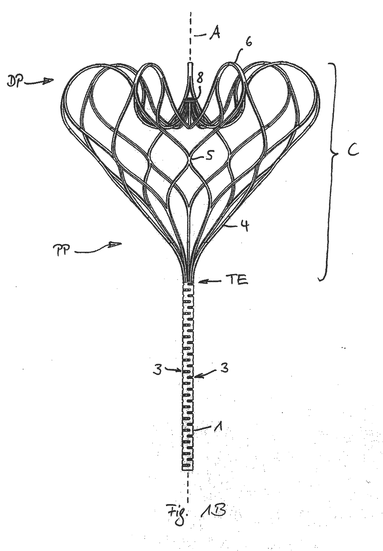
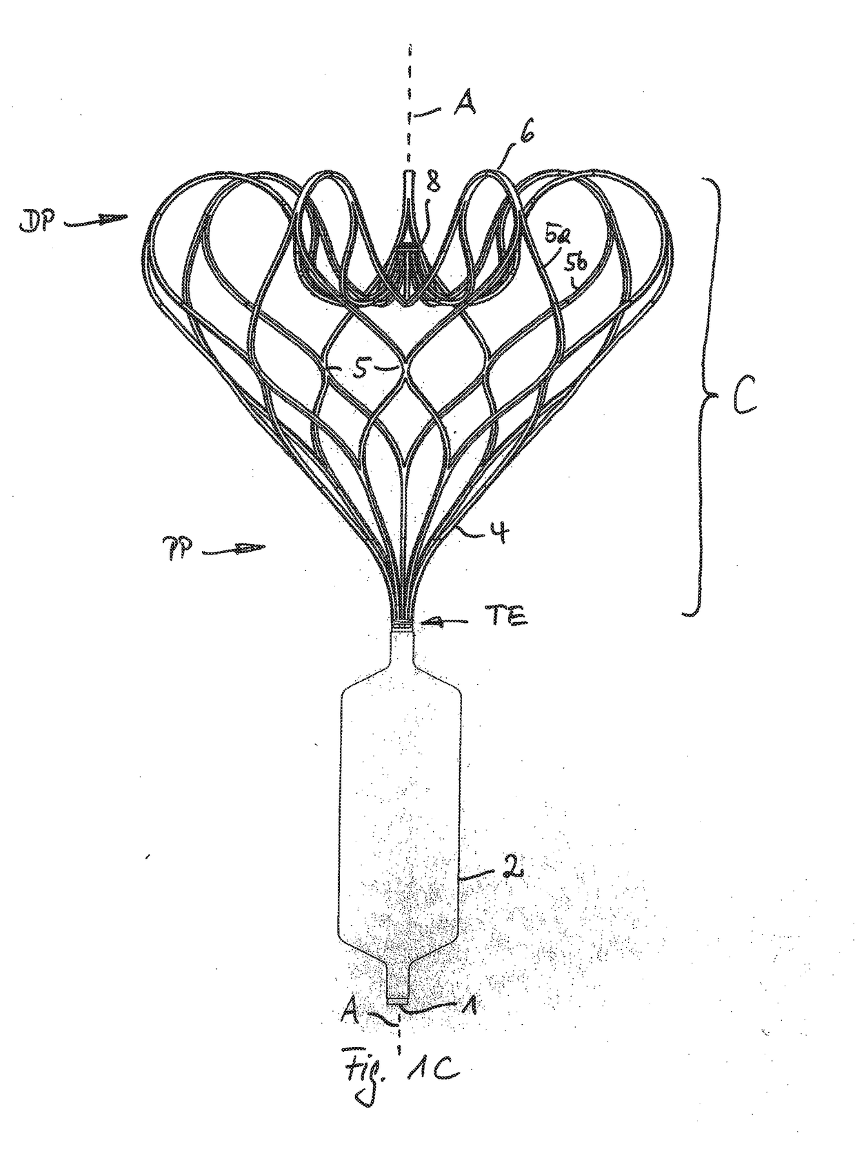
[0047]FIG. 1A show a side view of the implant without attached membrane. For better visibility and better explanation only the lines lying in front of the paper plane are shown. Some of the following reference numerals are shown in FIG. 1a only. FIG. 1B shows the same view and all lines. FIG. 1C shows the entire device with a membrane attached to the attachment element. The following description applies for all FIGS. 1A, 1B, 1C.

[0048]The lower part of the implant forms an attachment element 1 to which the membrane 2 (shown in FIG. 1C only) may be attached. Membrane 2 and attachment element 1 form a closure element that may be positioned in the annular area of a heart valve like the mitral valve. Even without the membrane 2 attached the shown device forms an implant according to the invention.

[0049]The attachment element 1 is formed of a single tube, preferably made of nitinol. Prefera...


PUM


Abstract

The invention relates to a heart implant comprising a tubular attachment element (1) for attaching an inflatable membrane (2), particularly an inflatable membrane (2) being coaxially positioned around the tubular attachment element (1) and fixed to it, the tubular attachment element (1) at one of its ends being split into several strips (4), the strips (4) extending away from the tubular attachment element (1) and forming an expandable cage (C), particularly for fixing the heart implant to the atrium of the heart by surface contact between an exterior surface of the expandable cage (C) and an interior atrium surface, each one of the strips (4) being split into two branches (4a, 4b, 4a′, 4b′, . . . ), each respective branch (4a) being merged into a new strip (5) together with another respective branch (4b′) of a neighboring strip (4) wherein such splitting and merging is performed one after the other at least three times and the number of strips (7) being formed of the last merged branches (6a, 6b, . . . ) at the end of extension corresponding to the number of strips (4) at the one end of the tubular attachment element (1).

Description

TECHNICAL FIELD[0001]The invention relates to a heart implant, particularly a heart implant being configured to reduce or eliminate a heart valve insufficiency after implantation into the heart.BACKGROUND OF THE INVENTION[0002]Typically such implants are positioned in such a way that a closure element of the implant is situated in the valve annulus and closes a remaining gap of the closed valve leaflets. For that purpose the closure element is connected to an anchoring element being configured to fix the closure element within the heart in the desired position i.e., in the valve annulus preferably to be contacted by the closing valve leaflets.[0003]It is known in the art to use an anchoring element punctured into the myocardium for fixation of the closure element. Besides this invasive way modern implants provide a less invasive fixation just by contacting the interior wall of the atrium with the outer surface areas of an expanded cage that is connected to the closure element. Such ...

Claims


Application Information

Patent Timeline
Patent Type & Authority Applications(United States)
IPC IPC(8): A61F2/24
CPCA61F2/246A61F2/2463A61F2220/0008
Inventor NATHE, NIKLAS MAXIMILIANSCHEUERMANN, TORSTEN
Owner CORAMAZE TECH GMBH
Why Eureka
Try Eureka