

Urethane bumper spring, and method for producing same
a bumper spring and urethane technology, applied in the direction of suspensions, shock absorbers, other domestic articles, etc., can solve the problems that the urethane bumper spring is difficult to apply to a general type of vehicle, and achieve the effects of high load, high deformation, and excellent durability and settling resistan
- Summary
- Abstract
- Description
- Claims
- Application Information
AI Technical Summary
Benefits of technology
Problems solved by technology
Method used
Image

Examples
example 1
[0058]A liquid A formed of 100 parts by weight of a polyol agent, 11.8 parts by weight of a chain extender, 1.1 parts by weight of a catalyst, and 0.6 part by weight of a foaming agent was prepared. In addition, a liquid B formed of 169.3 parts by weight of an isocyanate agent was prepared. Next, a die (master mold and core) capable of forming a cavity having the same shape as a bumper spring 40 as illustrated in FIG. 4 was prepared. Then, the master mold and the core were combined to form the predetermined forming cavity, and then the die formed of the master mold and the core was heated. Subsequently, the liquid A and the liquid B were stirred at 3,000 rpm for 5 seconds (liquid temperature: 40±1° C., NCO index: 1.0), and then the mixture was injected into the die and subjected to primary vulcanization for 10 minutes while the temperature of the die was kept at 70° C. Then, the urethane molded body after the primary vulcanization was demolded from the die, and further subjected to ...
PUM
| Property | Measurement | Unit |
|---|---|---|
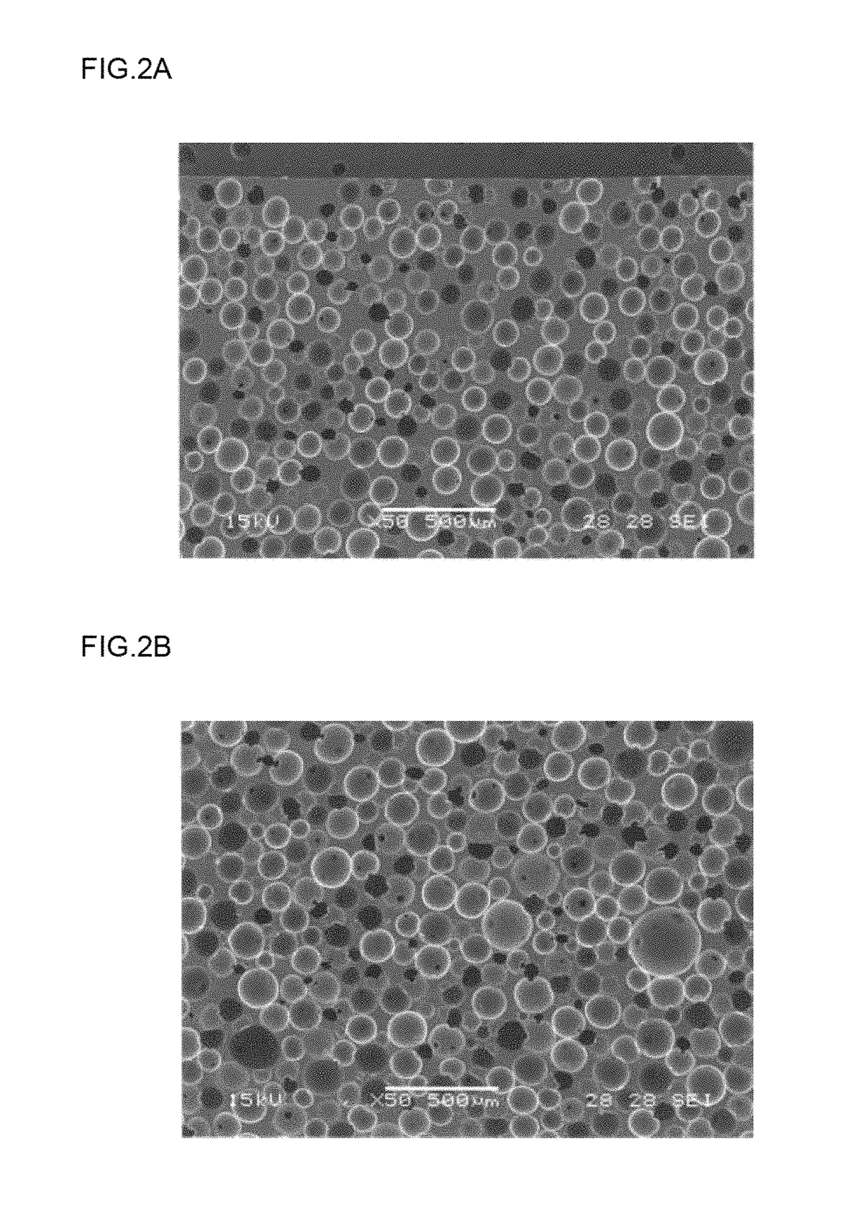
| density Db | aaaaa | aaaaa |
| cell diameter Ra | aaaaa | aaaaa |
| cell diameter Rb | aaaaa | aaaaa |
Abstract
Description
Claims
Application Information