Glazing system with thermal break

a technology of thermal break and glazing system, which is applied in the direction of glass pane fixing, wing frames, balusters, etc., can solve the problems of laborious, complicated work, and eventually expensiv

Active Publication Date: 2017-06-20
CITY GLASS & GLAZING PTE LTD
View PDF46 Cites 23 Cited by
  • Summary
  • Abstract
  • Description
  • Claims
  • Application Information

AI Technical Summary

Benefits of technology

The patent aims to solve the problems of complicated and expensive screw fastening for thicker glass applications while ensuring safety and aesthetic appeal. It emphasizes the need for faster glazing and makes the installation process easy by providing enough clearance for glass size and simplifying the installation process.

Problems solved by technology

These profiles are used by many people for bigger partition walls with thicker glazing, compromising safety, quality and aesthetic appeal as no other options are available for glazing big partition walls with thicker glass panel than window pane glasses.
Technicians use U channels, in which glass panels are allowed to stand free but these tend to move horizontally due to loose fixing with silicone at the ends.
Some professional pioneers like Dorma (Germany) developed heavy profiles for thicker glass application which require fastening by screws that further should be covered for aesthetic reasons and consequently the work becomes complicated, laborious and eventually expensive.

Method used


Image

  • Glazing system with thermal break
  • Glazing system with thermal break
  • Glazing system with thermal break

Examples


Embodiment Construction

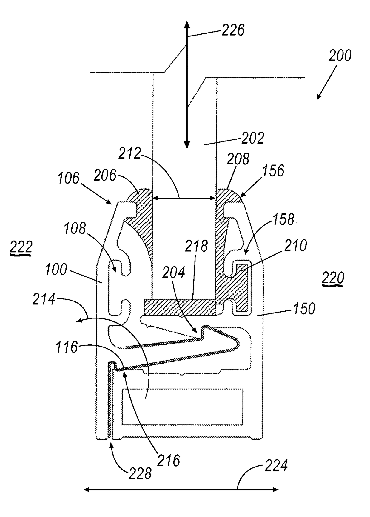
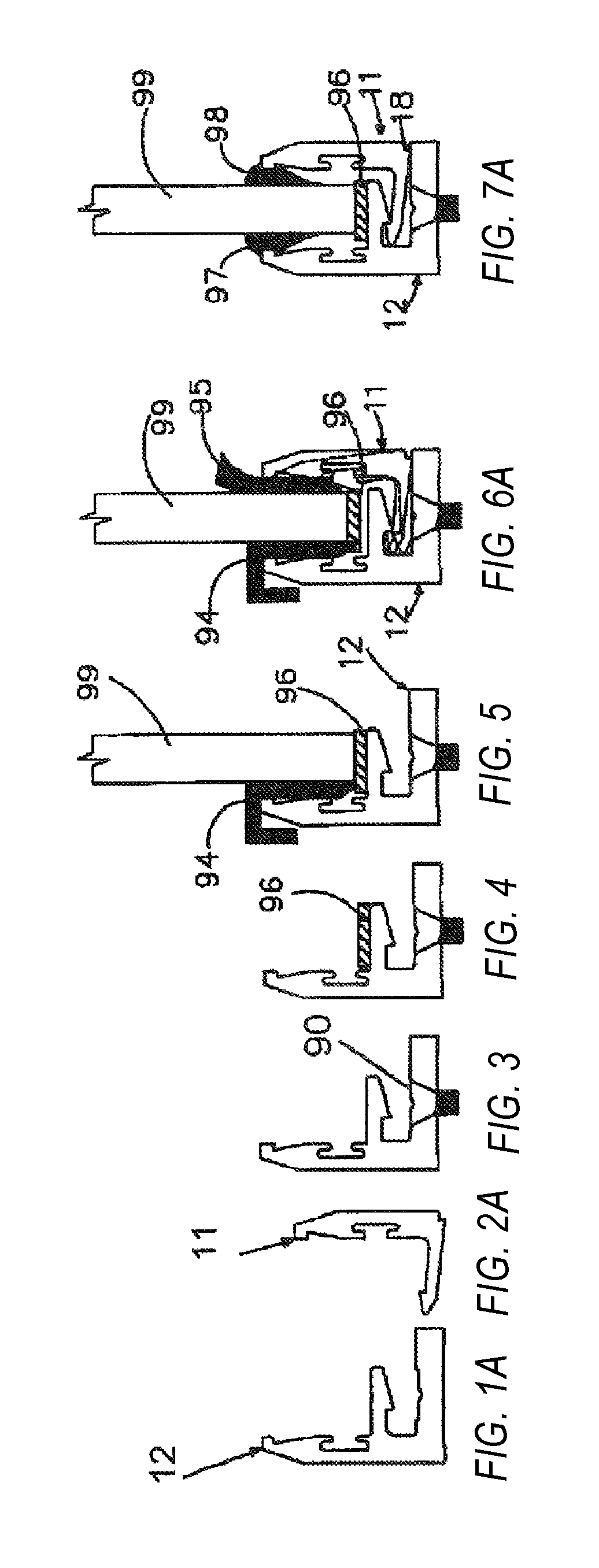
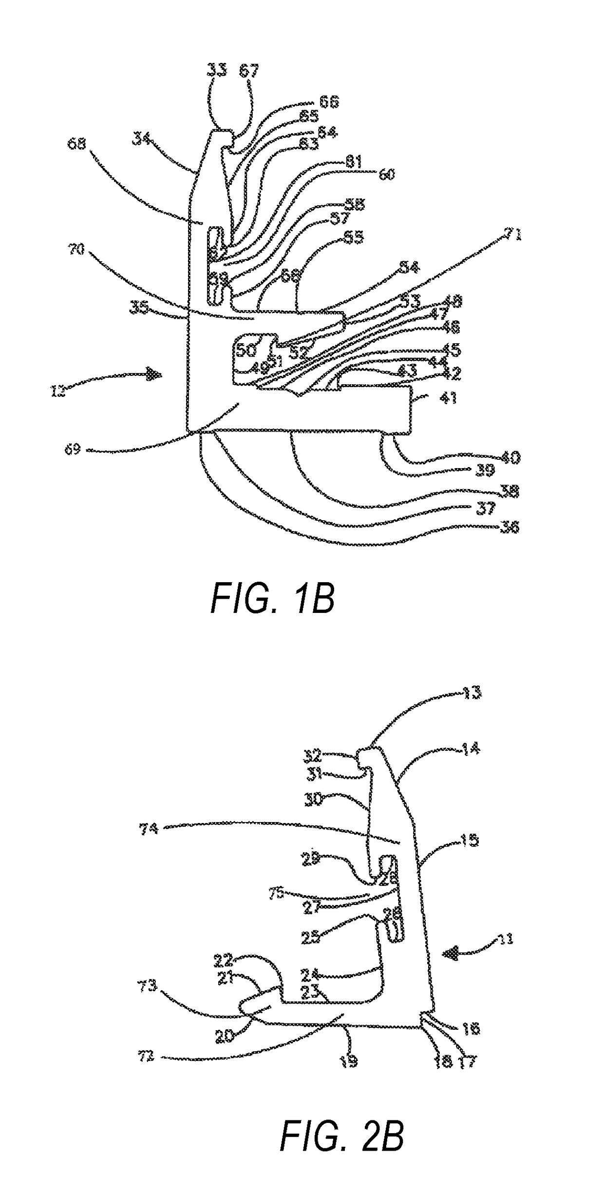
[0042]The self-lock glazing system consists of two extruded aluminum profiles, a male profile 11, FIG. 2A and a female profile 12, FIG. 1A as described in the succeeding paragraphs, designed in such a way to create a secure space for keeping glass panels safely and tightly in position. An important aspect is that when a glass panel 99, FIG. 7A is placed on the upper leg 70 of the female profile 12 and the male profile 11 is inserted and rubber beadings 97, 98 are forced in (by hand) between the said glass panel 99 and the profiles 12, 11 respectively creates outward forces F, FIG. 8 on the vertical tips of the said profiles (forcing them apart). The turning moment at the pivotal fulcrum 18 of the said male profile 11 forces the locking system together because of the complementary locking tips 73 and 71 provided on the profiles as a result, the system interlocks and thus arrest the profiles (11 and 12) in position; eventually the said glass panel 99 held in guard (under the pressure ...


PUM


Abstract

A self-locking glazing system includes a female profile having a first locking extension and a first leg extending therefrom, the first leg having a first tip. The system includes a male profile having a second locking extension and a second leg extending therefrom, the second leg having a second tip that is approximately opposite the first tip, and a thermal break material positioned between the female and male profiles. When a panel is positioned between the first and second tips, the female profile and the male profile are caused to engage against the thermal break material.

Description

CROSS-REFERENCE TO RELATED APPLICATIONS[0001]This application is a continuation-in-part of U.S. patent application Ser. No. 14 / 148,188, filed on Jan. 6, 2014, which claims the benefit of U.S. patent application Ser. No. 12 / 261,891, filed on Oct. 30, 2008, which is a continuation-in-part of U.S. patent application Ser. No. 10 / 566,536, filed Jan. 30, 2006, which claims priority to International Application No. PCT / IB2004 / 002298, filed Jul. 15, 2004, which are incorporated herein by reference in their entirety.BACKGROUND[0002]1. Field[0003]The current disclosure relates to a unique and compact self-lock glazing system composed of two aluminum extrusion profiles—a male profile and a female profile—designed in such a way to self-lock glass panels using beadings. The mechanism functions when a glass panel is positioned on setting blocks over the flat surface of the upper leg of the said female profile—with spacers between the vertical leg of the said female profile and the said glass pane...

Claims


Application Information

Patent Timeline
Patent Type & Authority Patents(United States)
IPC IPC(8): E06B3/54E06B3/663E06B3/58E06B3/24
CPCE06B3/549E06B3/5821E06B3/66304E06B3/24E06B2003/5472Y10T29/49826Y10T29/49959E04F11/1812E04F11/1846E04F11/1853E04F2011/1895
Inventor ABDUL LATHIEF, ARAKKAL ABDUL KHADER
Owner CITY GLASS & GLAZING PTE LTD
Why Eureka
Try Eureka