
System and method for sludge removal in a circular settling tank

a settling tank and settling tank technology, applied in the direction of gearing, separation process, hoisting equipment, etc., can solve the problems of difficult roof installation, inability to install inclined settling plate packs in the settling tank in order to increase the settling capacity, etc., to achieve simple, more economical and reliable sludge scrapers

Active Publication Date: 2017-07-04
NORDIC WATER PROD AB
View PDF20 Cites 0 Cited by
  • Summary
  • Abstract
  • Description
  • Claims
  • Application Information

AI Technical Summary

Benefits of technology

[0007]An object of the present invention is to provide a system and a method of the kind initially mentioned, wherein the drawbacks of prior art are eliminated or at least minimized. Thus, an object is to provide much simpler, more economical and more reliable sludge scrapers for circular tanks.
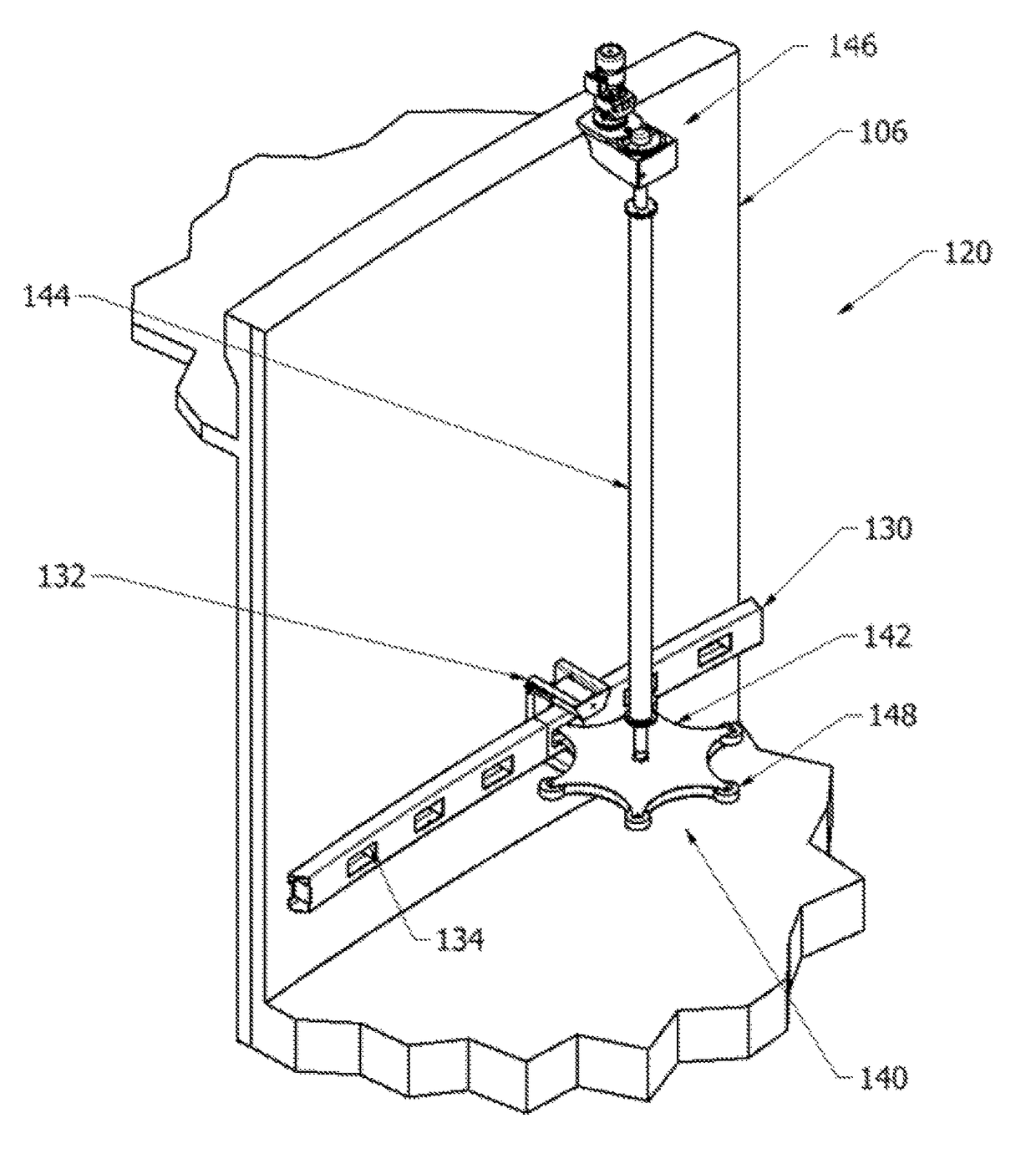
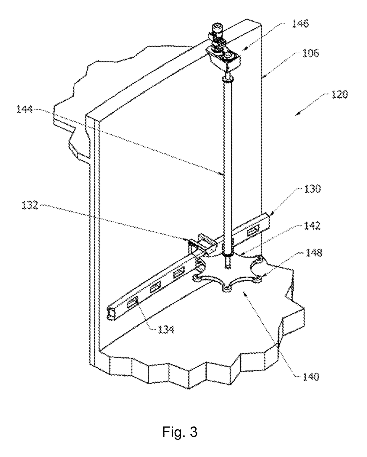
[0009]In a preferred embodiment, the engagement surfaces are planar. In this way, the engagement rolls can roll on the engagement surfaces while minimizing the radial forces on the drive ring.
[0010]In a preferred embodiment, the engagement surfaces extend radially from the centre of the drive ring, further minimizing the radial forces on the drive ring.
[0012]In a preferred embodiment, six engagement rolls are provided at equal distance from the centre of the drive wheel and at an equal mutual distance. This number of engagement rolls provides good drive characteristics for the drive ring.
[0014]By use of the described system and method, much simpler, more economical and more reliable sludge scrapers for circular tanks can be achieved.

Problems solved by technology

For instance, in winter snow and ice will interfere with the operation, the peripheral drive makes it difficult to provide a roof over the settling tank and the truss makes it impossible to install inclined settler plate packs in the settling tank in order to increase settling capacity.

Method used


Image

  • System and method for sludge removal in a circular settling tank
  • System and method for sludge removal in a circular settling tank
  • System and method for sludge removal in a circular settling tank

Examples


Embodiment Construction

[0024]In the following, a detailed description of a method and a system for sludge removal from circular tanks will be given.

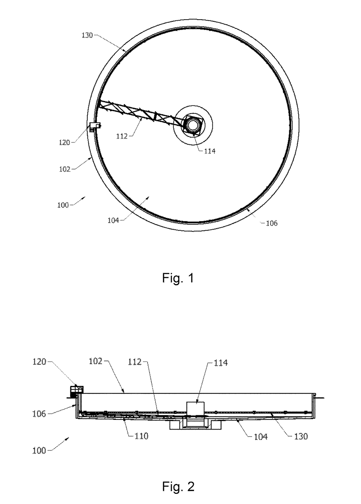
[0025]FIGS. 1 and 2 show an overall view of a system according to the invention, generally designated 100. The system, which is mounted in a circular settling tank 102 having a slanting or horizontal bottom 104 an essentially circular side wall 106, as is conventional. The system further comprises blades 110 attached to an arm 112 which in turn is attached to a vertical stub shaft 114. Optionally, skimmers (not shown) are also attached to the arm 112 or alternatively to the stub shaft 114.

[0026]Reference will now be made to FIG. 3, which is an enlarged view of a drive arrangement 120 and which shows part of the circular wall 106 and the bottom 104.

[0027]Suspended to the side wall 106, there is provided a rotatable drive ring 130 which runs all around the side wall and which is part of a drive arrangement, generally designated 120. The drive ring 130 may be att...


PUM

PropertyMeasurementUnit
distanceaaaaaaaaaa
mutual distanceaaaaaaaaaa
radiusaaaaaaaaaa

Abstract

A system for sludge removal in a circular settling tank having a side wall (106) comprises a rotatable drive ring (130) adapted to be interconnected to a scraper arm provided with scraper blades, wherein the drive ring having a plurality of engagement surfaces (134) A traction assembly (140) is fixedly attached to the side wall and comprises a drive wheel (142). By providing a drive wheel with a plurality of engagement rolls (148) adapted to engage the engagement surfaces of the drive ring during rotation of the drive wheel, the drive ring can be rotated essentially without exerting any radial forces on the drive ring.

Description

TECHNICAL FIELD[0001]The present invention relates generally to a method and a system for sludge removal in a circular settling tank.BACKGROUND ART[0002]Circular settling tanks are commonly used for treatment of water and wastewater. Water containing particles is introduced into the settling tank and the particles will settle to the bottom of the settling tank where they will form a sludge layer. The influent to the settling tank is divided into an overflow and an underflow. Settling tanks are expected to produce a reasonably clean overflow and a reasonably thick underflow. If the emphasis is on the clean overflow they are often named clarifiers and if the emphasis is on a thick underflow they are often named thickeners. The underflow normally leaves the settling tank through a central outlet in the bottom of the tank. The sludge that has collected on the tank bottom is transported to the underflow outlet by means of at least one sludge scraper. A sludge scraper normally consists of...

Claims


Application Information

Patent Timeline
Patent Type & Authority Patents(United States)
IPC IPC(8): B01D21/20B01D21/06B01D21/24F16H55/17B01D21/18F16H55/10F16H19/04
CPCB01D21/06B01D21/18B01D21/20B01D21/245F16H55/10F16H55/17F16H19/04
Inventor LJUNGBERG, BERTIL
Owner NORDIC WATER PROD AB
Learn More