Conduction breaking device

a technology of breaking device and breaking device, which is applied in the direction of capacitor severing switch, explosion-operated switch, electrical apparatus, etc., can solve problems such as insufficient attenuation of ar

Active Publication Date: 2017-07-11
TOYODA GOSEI CO LTD
View PDF17 Cites 6 Cited by
  • Summary
  • Abstract
  • Description
  • Claims
  • Application Information

AI Technical Summary

Benefits of technology

[0011]Accordingly, it is an objective of the present invention to provide a conduction breaking device that restrains an arc from flowing outside an arc-extinguishing chamber.

Problems solved by technology

In this case, the arc may not be properly attenuated.

Method used


Image

  • Conduction breaking device
  • Conduction breaking device
  • Conduction breaking device

Examples


first embodiment

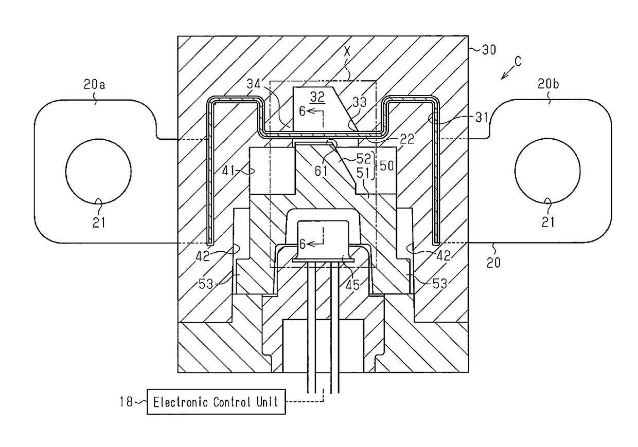
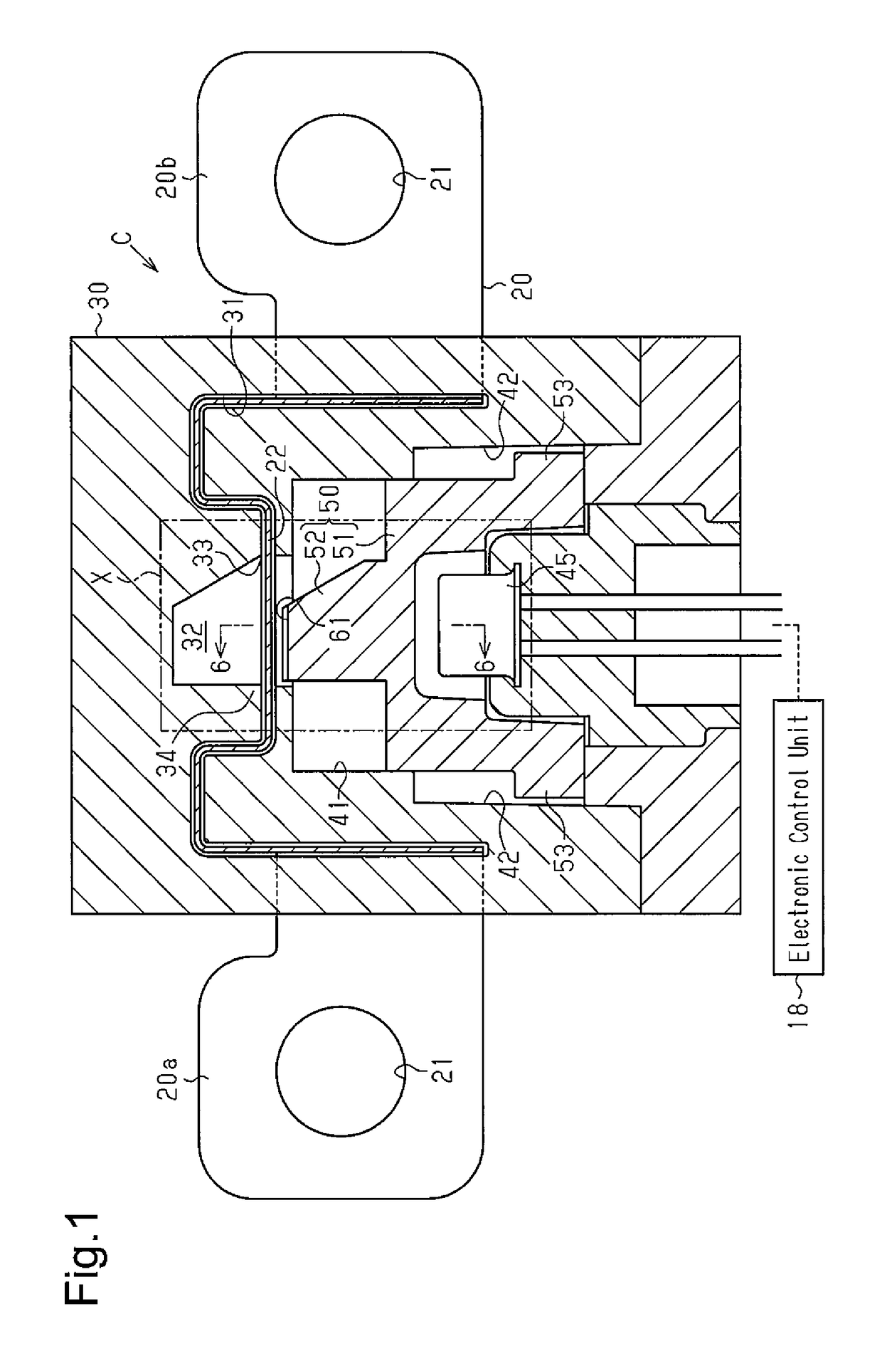
[0039]A conduction breaking device C for a vehicle according to a first embodiment will now be described with reference to FIGS. 1 to 10.

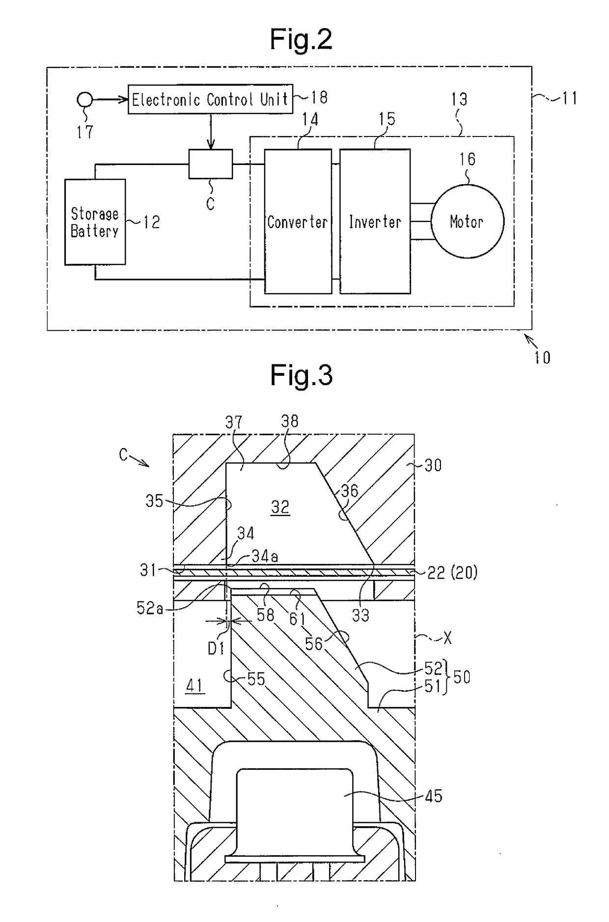
[0040]FIG. 2 shows an electric circuit 11 in which the conduction breaking device C is incorporated. The electric circuit 11 includes as its components a storage battery 12 and an electric device 13. In the electric circuit 11, the electric device 13 is operated by power supplied from the storage battery 12. The electric device 13 is configured by a converter 14, which increases the voltage of the power delivered from the storage battery 12 and outputs power of the increased voltage, an inverter 15, which converts DC power from the converter 14 into AC power suitable for driving a motor and outputs the AC power, and a motor 16, which is driven by the AC power output from the inverter 15.

[0041]The electric circuit 11 is mounted on a vehicle 10. When the vehicle 10 receives an impact due to a collision, the electric device 13 may not properly operate...

second embodiment

[0085]Next, a conduction breaking device C for a vehicle according to a second embodiment will now be described with reference to FIGS. 11A to 13B.

[0086]As shown in FIGS. 11A, 11B, and 12, a cutting delaying portion is not provided in the movable blade 52, but provided in the fixed blade 34 in the second embodiment. That is, in the second embodiment, the cutting delaying portion is provided in a different portion from that in the first embodiment.

[0087]Specifically, a second cutting delaying portion 62 in the second embodiment is provided in the cutting edge 34a of the fixed blade 34 at the central portion in the width direction of the cuttable portion 22. The second cutting delaying portion 62 is constituted by a recess that is recessed toward the leading side (the upper side as viewed in FIGS. 11A, 11B, and 12) in the moving direction of the movable blade 52.

[0088]The cutting edge 52a of the movable blade 52 does not have such a recess, but has a straight structure along the width...

third embodiment

[0097]Next, a conduction breaking device C for a vehicle according to a third embodiment will now be described with reference to FIGS. 14, 15A, and 15B.

[0098]As shown in FIGS. 15A and 15B, a cutting delaying portion is not provided in the movable blade 52 or the fixed blade 34, but is provided in the cuttable portion 22 in the third embodiment. That is, in the third embodiment, the cutting delaying portion is provided in a different portion from those in the first and second embodiments.

[0099]As shown in FIGS. 14 and 15B, the central portion of the section-to-be-cut of the cuttable portion 22 in the width direction is located closer to the leading side in the moving direction of the movable blade 52 (the upper side as viewed in FIGS. 14, 15A, and 15B) than the other sections. The central part constitutes a third cutting delaying portion 63 of the third embodiment.

[0100]The third cutting delaying portion 63 is formed, for example, in the following manner. First, two slits, which exte...


PUM


Abstract

The conduction breaking device includes a conductive body, a fixed blade, an arc-extinguishing chamber, a gas generator, a cutting member, and a cutting delaying portion. The fixed blade and the arc-extinguishing chamber are located on one side of the cuttable portion with respect to a thickness direction of the cuttable portion in the conductive body. The gas generator is located on the opposite side of the cuttable portion with respect to the thickness direction. The cutting member is arranged between the cuttable portion and the gas generator and includes a movable blade. The cutting delaying portion is provided at the movable blade and configured to allow a part of an area of the cuttable portion that is, in the width direction, closer to the center than the edges are to the center to be cut after the other parts are cut.

Description

BACKGROUND OF THE INVENTION[0001]The present invention relates to a conduction breaking device that breaks conduction between two devices constituting an electric circuit by cutting a conductive body extending between the devices.[0002]Some electric circuits are provided with a conduction breaking device for breaking conduction between devices by being activated when a malfunction occurs in a device in the electric circuit or in a system on which the electric circuit is mounted. As one form of such conduction breaking devices, Japanese Laid-Open Patent Publication No. 2014-49300 discloses a conduction breaking device C shown in FIGS. 16A and 16B, which includes a conductive body 80, a gas generator (not shown), a fixed blade 84, and a cutting member 85.[0003]The conductive body 80 includes an elongated plate-shaped cuttable portion 81 and is arranged between devices that constitute an electric circuit. The gas generator is arranged on one side of the cuttable portion 81 with respect...

Claims


Application Information

Patent Timeline
Patent Type & Authority Patents(United States)
IPC IPC(8): H01H39/00B60L50/15
CPCH01H39/006H01H2039/008
Inventor FUKUYAMA, TAKAKINAKAMURA, YOSHIKIHORI, KEISUKE
Owner TOYODA GOSEI CO LTD
Why Eureka
Try Eureka