
On-vehicle radar device and vehicle

a technology for vehicle radar and vehicle, applied in waveguide horns, instruments, reradiation, etc., to achieve the effect of suppressing the reduction in the efficiency of radio-wave transmission and reception

Inactive Publication Date: 2017-10-24
NIDEC CORP
View PDF15 Cites 3 Cited by
  • Summary
  • Abstract
  • Description
  • Claims
  • Application Information

AI Technical Summary

Benefits of technology

[0008]Preferred embodiments of the present invention provide an on-vehicle radar device, and are able to suppress or prevent a reduction in the efficiency of radio-wave transmission and reception when the on-vehicle radar device is arranged in the interior of a vehicle.
[0013]According to preferred embodiments of the present invention, it is possible to suppress a reduction in the efficiency of radio-wave transmission and reception in an on-vehicle radar device located in the interior of a vehicle.

Problems solved by technology

Accordingly, it was reasonable to select an installation angle that is slightly smaller than the Brewster angle because the installation angle could deviate from a predetermined angle due to limited accuracy of a mounting process.

Method used


Image

  • On-vehicle radar device and vehicle
  • On-vehicle radar device and vehicle
  • On-vehicle radar device and vehicle

Examples


Embodiment Construction

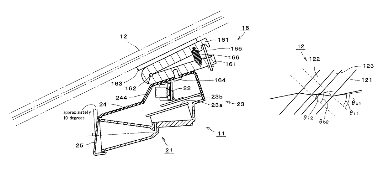
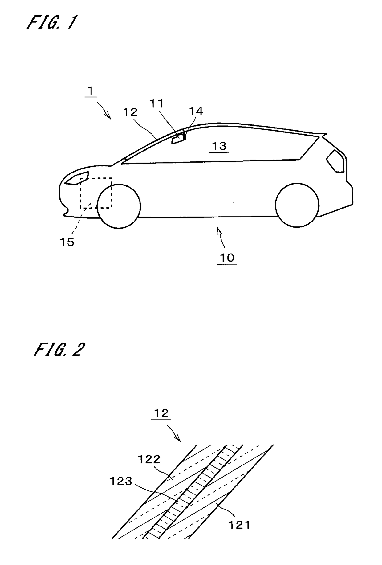
[0023]FIG. 1 is a simplified side view of a vehicle 1 according to an exemplary preferred embodiment of the present invention. The vehicle 1 is preferably, for example, a passenger car and includes an on-vehicle radar device 11 (hereinafter, referred to as a “radar device”).

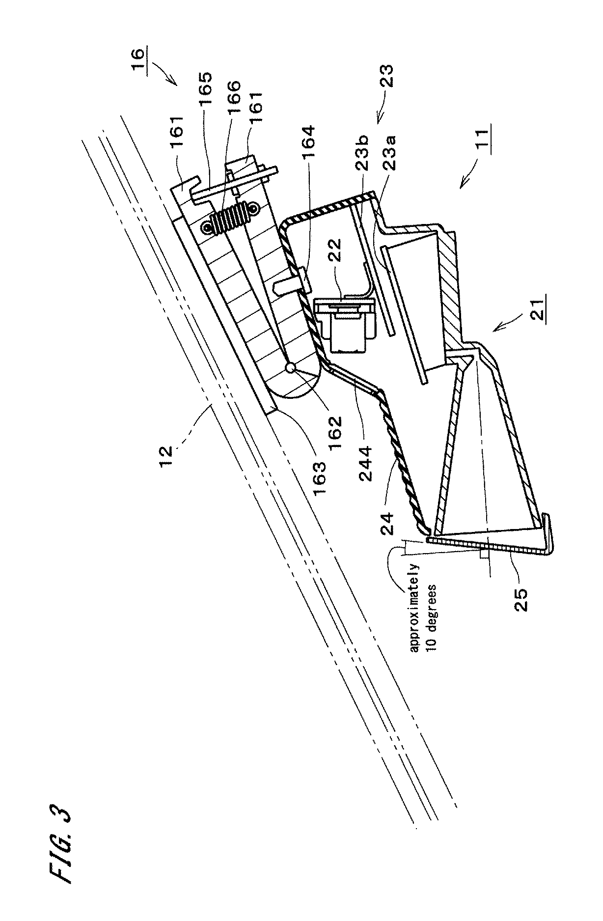
[0024]The radar device 11 is used for purposes such as, for example, collision avoidance, driving assistance, and automatic driving. The radar device 11 is mounted on the inner surface of a front windshield 12 of the vehicle 1 and located in a vehicle interior 13. The vehicle interior 13 does not need to be a completely isolated space separated from the outside, and may be open-roofed, for example. The radar device 11 is located forward of a rear-view mirror 14 mounted on the front windshield 12. The vehicle 1 preferably includes a drive mechanism 15 configured to move a vehicle body 10. The drive mechanism 15 is defined by, for example, an engine, a steering mechanism, a power transmission mechanism, wheels and ...


PUM


Abstract

An on-vehicle radar device includes a mount and an antenna configured to transmit a transmission wave from an inner side of laminated glass, which includes an innermost glass layer, an outermost glass layer, and an intermediate resin layer, and receive a reflected wave. The antenna includes a transmitting antenna. When the mount is mounted on a bracket, the incident angle of the transmission wave on the innermost glass layer is greater than a Brewster angle on the inner surface of the innermost glass layer, and the incident angle of the transmission wave on the outermost glass layer is less than or equal to a Brewster angle between the outermost glass layer and the intermediate resin layer.

Description

BACKGROUND OF THE INVENTION[0001]1. Field of the Invention[0002]The present invention relates to an on-vehicle radar device and a vehicle.[0003]2. Description of the Related Art[0004]Research has been conducted in recent years into areas such as collision avoidance, driving assistance, and automatic driving, utilizing technology that uses radar to detect objects around a vehicle. In the case of a car, the radar has conventionally been provided on the front nose. A high-frequency oscillator needs to be placed in the vicinity of an antenna and requires water and weather proofing measures, such as protection using a radome (i.e., a radio dome), to avoid wind and rain. Meanwhile, more sophisticated detection technology has also been developed, using both radar detection and camera images.[0005]U.S. Pat. No. 8,604,968 proposes a radar-camera sensor in which a radar and a camera are housed in a single housing. The radar-camera sensor is mounted on the front windshield of a car forward of ...

Claims


Application Information

Patent Timeline
Patent Type & Authority Patents(United States)
IPC IPC(8): H01Q1/32H01Q13/02H01Q1/42G01S13/02G01S7/02G01S7/03G01S13/86G01S13/93H01Q1/12G01S13/931
CPCH01Q1/3266G01S7/024G01S7/032G01S13/02G01S13/867H01Q1/1271H01Q1/3233H01Q1/422H01Q13/02G01S13/931G01S2013/9392G01S2007/027B32B17/10036G01S2013/93276G01S7/027
Inventor KAMO, HIROYUKI
Owner NIDEC CORP
Learn More