Printing apparatus

a printing machine and roller transfer technology, applied in printing, other printing machines, thin material processing, etc., can solve the problems of uneven load of the press on the medium, roller transfer scratches and nip marks on the medium,

Active Publication Date: 2018-03-13
SEIKO EPSON CORP
View PDF9 Cites 0 Cited by
  • Summary
  • Abstract
  • Description
  • Claims
  • Application Information

AI Technical Summary

Benefits of technology

[0020]According to this configuration, since one roller shaft is caused to swing along the pressing direction in which the first driven roller and the second driven roller press the medium on the driving roller, it is possible to appropriately suppress pressing force at which the first driven roller and the second driven roller press the medium due to swinging of the roller shaft.

Problems solved by technology

As a result, in a case where the plurality of driven rollers are attached to one roller shaft, there is a problem in that load which presses on the medium is not uniform and roller transfer scratches and nip marks are generated on the medium.

Method used


Image

  • Printing apparatus
  • Printing apparatus
  • Printing apparatus

Examples


Embodiment Construction

[0036]An embodiment of a printing apparatus will be described below with reference to the drawings. For example, the printing apparatus is a large format printer which performs printing (recording) on a long medium.

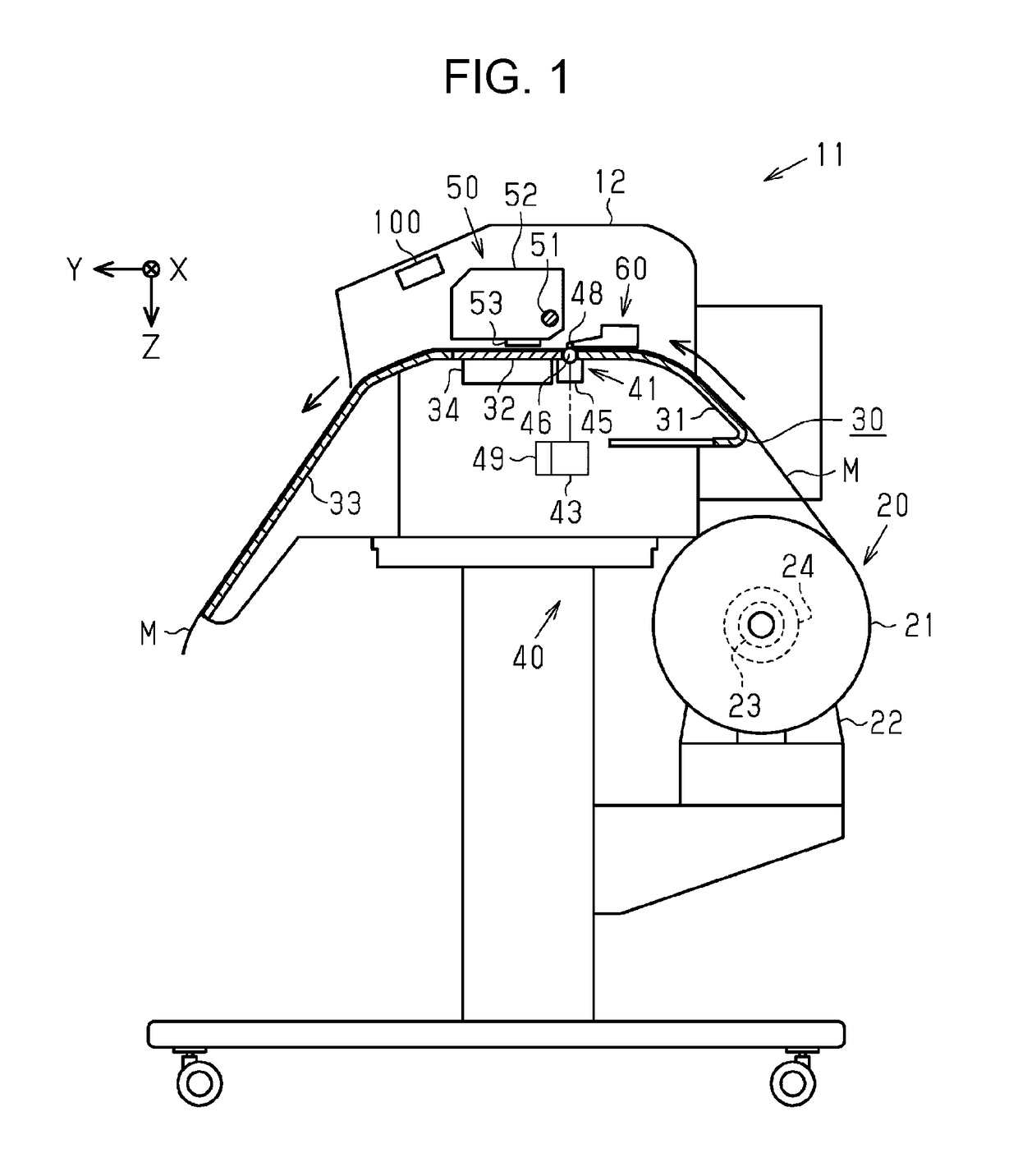
[0037]As shown in FIG. 1, a printing apparatus 11 is provided with a chassis portion 12, a medium support portion 30 which supports a medium M, a transport device 40 which transports the medium M in a direction indicated by an arrow in FIG. 1, and a printing portion 50 which performs printing on the medium M within the chassis portion 12.

[0038]Hereinafter in the description, one direction along a width direction (direction which is orthogonal to a paper surface in FIG. 1) which is orthogonal to a longitudinal direction of the medium M is set as a scanning direction X and a direction in which the medium M is transported at a position at which the printing portion 50 performs printing is set as a transport direction Y. In the embodiment, the scanning direction X and the tra...


PUM


Abstract

A printing apparatus includes a printing portion for printing on a medium, a driving roller for transporting the medium, a first and a second driven roller which are respectively supported with a gap in one roller shaft in a shaft line direction of the roller shaft and rotate around the roller shaft while pressing the transported medium on the driving roller, and a shaft support member that has a shaft support portion which supports the roller shaft between the first driven roller and the second driven roller. The first and the second driven roller have a through hole into which the roller shaft is inserted and an inner diameter in a roller center portion is smaller than an inner diameter of a roller end portion in the shaft line direction. The roller shaft is supported so as to be swingable with the shaft support portion as a support point.

Description

BACKGROUND[0001]1. Technical Field[0002]The present invention relates to a printing apparatus which transports a medium that is a printing target.[0003]2. Related Art[0004]A printer which is an example of a printing apparatus has a driving roller which transports a medium to a printing portion, and a plurality of driven rollers which are supported to be rotated respectively to one end side and another end side of one roller shaft and transport the transported medium with interposed between the driving roller and the driven roller by being rotated while pressing the medium on the driving roller.[0005]In such a printer, it is possible to hold a revolving shaft of the driving roller and a revolving shaft of the driven roller in parallel by setting a form of a hole which is provided in the driven roller, in which the roller shaft is insertable, as a taper form in which the inner diameter is small in a center portion with respect to a shaft direction and becomes larger accompanying movem...

Claims


Application Information

Patent Timeline
Patent Type & Authority Patents(United States)
IPC IPC(8): B41J13/03
CPCB41J13/03B41J11/007B41J15/04B65H5/06B65H2404/134B65H2404/135
Inventor AOKI, HIROKITOKAI, YOSHITSUGU
Owner SEIKO EPSON CORP
Why Eureka
Try Eureka