

Indirect spot welding apparatus
a welding apparatus and spot welding technology, applied in the direction of resistance electrode holders, manufacturing tools, transportation and packaging, etc., can solve the problems of large electrode force that cannot be applied to the overlapping metal sheet, excessive pressing force is momentarily applied to the welded portion, and overshoot of pressing force, etc., to achieve accurate control of pressing force, stable setting, satisfactory strength
- Summary
- Abstract
- Description
- Claims
- Application Information
AI Technical Summary
Benefits of technology
Problems solved by technology
Method used
Image

Examples
example 1
[0058]EXAMPLE 1 of the present invention will be described.
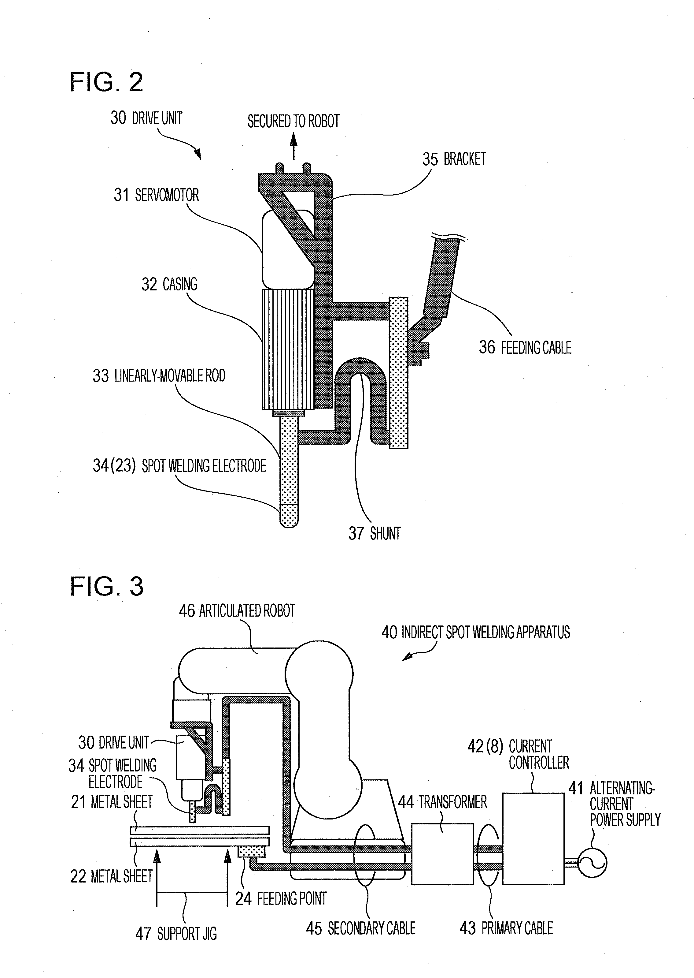
[0059]EXAMPLE 1 examined the performance of each of drive units (Drive Units 1 to 5) based on the drive unit having the configuration of FIG. 2 and mounted in the indirect spot welding apparatus of FIG. 3. Drive Units 1 to 5 are designed to specifications shown in Table 1.
[0060]In Table 1, a pressing force lower limit refers to a pressing force applied when the output of the servomotor 31 is 30% of the rated output, and a pressing force upper limit refers to a pressing force applied when the output of the servomotor 31 is 300% of the rated output.
[0061]Here, Drive Units 1 to 4 having pressing force lower limits ranging from 70 N to 200 N and pressing force upper limits ranging from 800 N to 2000 N are defined as Inventive Examples A to D, and Drive Unit 5 not having them is defined as Comparative Example A.
TABLE 1Pressing ForcePressing ForceServomotorBall ScrewLower Limit (N)Upper Limit (N)Size (W)Lead (mm)(Motor Output 30%)...
example 2
[0064]EXAMPLE 2 of the present invention will be described.
[0065]Drive Unit 2 shown in Tables 1 and 2 was used in EXAMPLE 2. The pressing force was set at 200 N and 800 N, and the electrode contact speed was varied from 10 mm / s to 80 mm / s. Then, an overshoot of the pressing force occurring when the spot welding electrode was pressed against the metal sheet was evaluated using OS in Equation (1) described above. The result is shown in Table 3.
[0066]Here, the cases where the electrode contact speeds were 10 mm / s, 20 mm / s, and 30 mm / s are defined as Inventive Example a, Inventive Example b, and Inventive Example c, respectively, and the cases where the electrode contact speeds were 40 mm / s, 60 mm / s, and 80 mm / s are defined as Comparative Example a, Comparative Example b, and Comparative Example c, respectively.
TABLE 3200 N800 NAveragePeakAveragePeakContactValueValueValueValueSpeedALPLOSALPLOS(mm / s)(N)(N)(%)(N)(N)(%)Remarks1020321567947910Inventive Example a202032177796787−1Inventive Ex...
example 3
[0068]EXAMPLE 3 of the present invention will be described.
[0069]In EXAMPLE 3, indirect spot welding of steel sheets (the upper steel sheet 21a and the lower steel sheet 22a) was performed as illustrated in FIG. 4 using the indirect spot welding apparatus 40 illustrated in FIG. 3.
[0070]Drive Units 1, 3, and 5 shown in Tables 1 and 2 were used as drive units, and a current controller of a direct-current inverter type was used as the current controller 8. The spot welding electrode 34 made of a chromium copper alloy and having a uniform curvature radius of 40 mm at an end thereof was used.
[0071]The upper steel sheet 21a and the lower steel sheet 22a were placed on a U-shaped metal support jig 47a illustrated in FIG. 4. The upper steel sheet 21a is an SPC270 steel sheet having a tensile strength of 270 MPa or more and a thickness of 0.7 mm, containing chemical components shown in Table 4, and having the balance of Fe and inevitable impurities. The lower steel sheet 22a is an SPC270 ste...
PUM
| Property | Measurement | Unit |
|---|---|---|
| Fraction | aaaaa | aaaaa |
| Fraction | aaaaa | aaaaa |
| Force | aaaaa | aaaaa |
Abstract
Description
Claims
Application Information