Contact and connecting device

a technology of connecting device and connector, which is applied in the direction of multi-conductor cable end pieces, coupling device connections, lighting and heating apparatus, etc., can solve the problem of unstable connection between the connector and the cold cathode fluorescent lamp, and achieve the effect of preventing damage or similar troubles

Inactive Publication Date: 2009-06-18
HOSIDEN CORP
View PDF7 Cites 8 Cited by
  • Summary
  • Abstract
  • Description
  • Claims
  • Application Information

AI Technical Summary

Benefits of technology

[0012]In this case, when the lead terminal of the electronic component is inserted between the clamp parts, the lead terminal is sandwiched between the clamp parts and the supporting part. This configuration significantly eases the attachment and removal of the lead terminal. Further, the base part has a substantially U shape in planar view or a substantially O shape in planar view, so that the base part can be stably set on a setting portion of the electronic equipment such as the circuit board. Therefore, the base part is advantageous in stably connecting and supporting the electronic component in midair. Moreover, the base part, the supporting part and the clamp parts, being plate bodies provided integrally, can be easily manufactured by press-molding or other processing, which leads to reduction in the cost of the contact.
[0027]It is preferable that the second connecting part is an annular body adapted to receive the end part of the main body of the electronic component. Such an annular second connecting part is easier to be sandwichingly held between the clamp parts and the supporting part of the contact.

Problems solved by technology

If the cold cathode fluorescent lamp is under vibrating conditions or the like, the connection between the connector and the cold cathode fluorescent lamp may become unstable.

Method used


Image

  • Contact and connecting device
  • Contact and connecting device
  • Contact and connecting device

Examples


Embodiment Construction

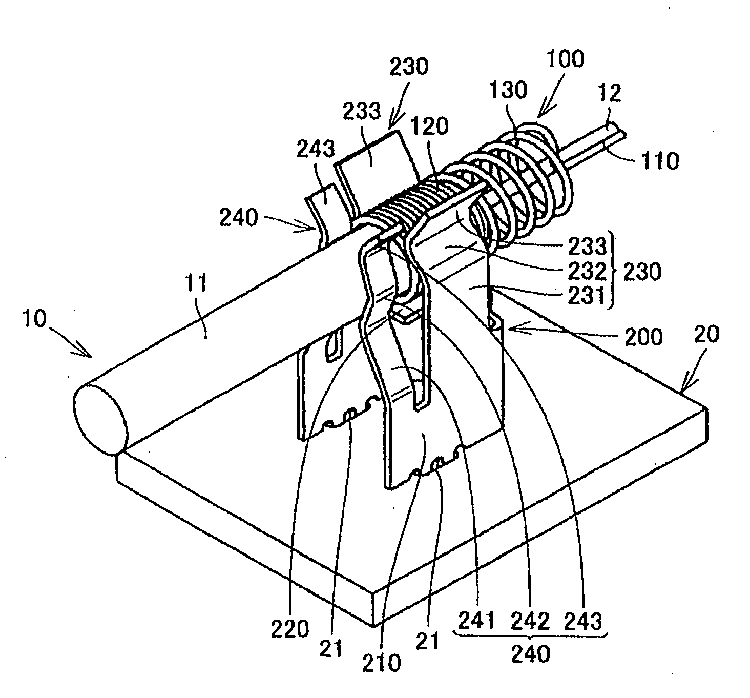
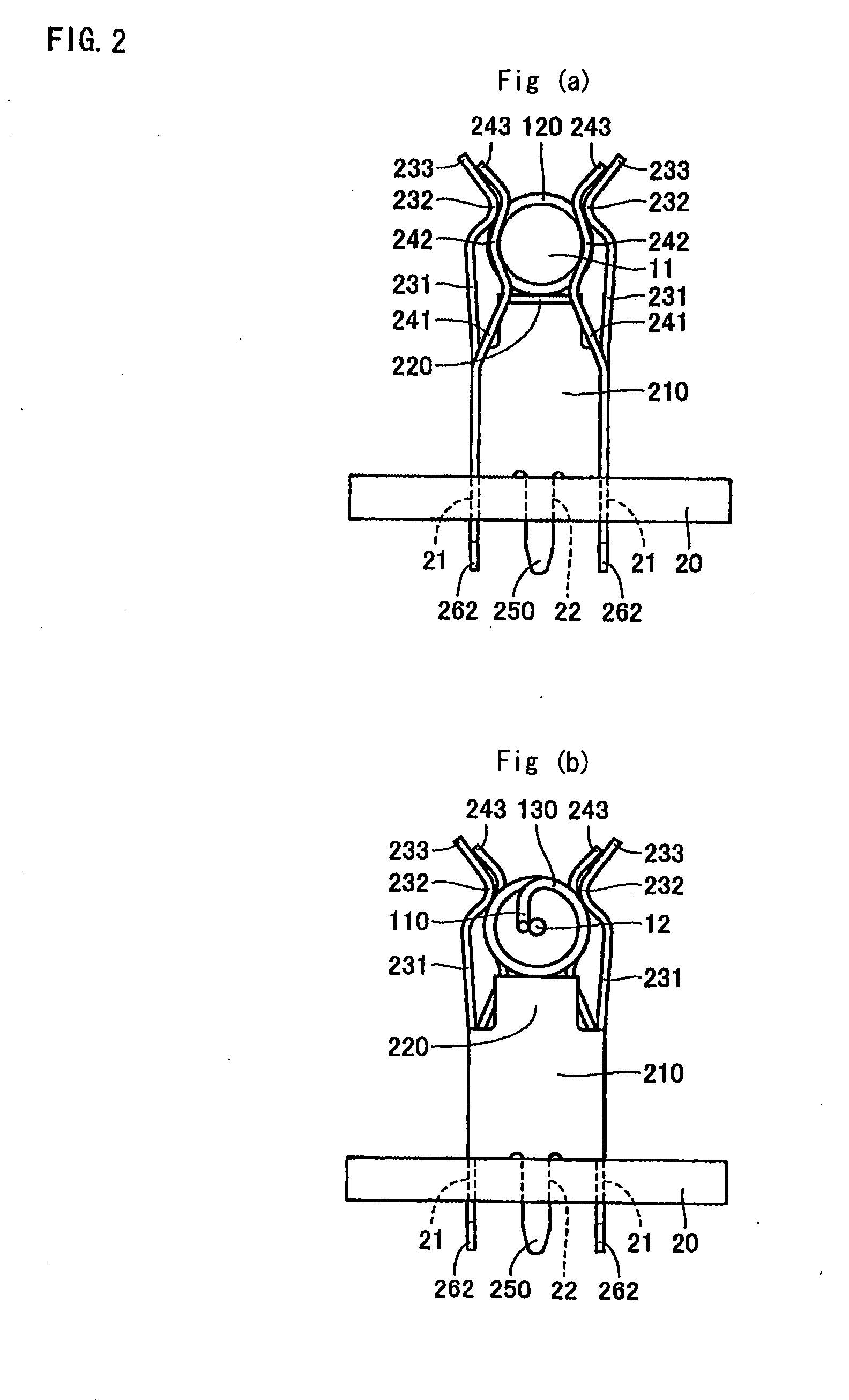
[0060]A connecting device according to an embodiment of the present invention will be described below with reference to FIGS. 1 to 6.

[0061]The connecting device illustrated in FIGS. 1 to 3 includes an adapter 100 to be connected to a lead terminal 12 of a cold cathode fluorescent lamp 10 (electronic component), and a contact 200 to be connected to the cold cathode fluorescent lamp 10 via the adapter 100 and mounted on a circuit board 20 of electronic equipment (not shown). Details of these elements will be described below.

[0062]The cold cathode fluorescent lamp 10 includes a lamp body 11 and a pair of lead terminals 12. The pair of lead terminals 12 are provided on respective end parts in the length direction of the lamp body 11 and extend in the length direction. For convenience of illustration, only one end part of the lamp body 11 is illustrated in FIGS. 1 to 3 and FIG. 6.

[0063]The adapter 100 is a coil spring having conductivity as illustrated in FIGS. 1 to 4. The adapter 100 in...


PUM


Abstract

The present invention provides a contact for connection with an electronic component. The contact includes: a base part; a supporting part, provided on top of the base part for supporting a lead terminal of the electronic component; and at least two clamp parts, provided on top of the base part so as to be located on respective outer sides of the supporting part. The clamp parts are adapted to sandwich the lead terminal of the electronic component between themselves and the supporting part.

Description

[0001]The present application claims priority under 35 U.S.C. §119 of Japanese Patent Application No. 2007-325,011 filed on Dec. 17, 2007, the disclosure of which is expressly incorporated by reference herein in its entity.BACKGROUND OF THE INVENTION[0002]1. Field of the Invention[0003]The present invention relates to a contact and a connecting device for connecting an electronic component such as a cold cathode fluorescent lamp.[0004]2. Description of the Related Art[0005]A known contact of this type has a pair of clamp pieces that sandwiches a cap-like adapter covering an end part of a cold cathode fluorescent lamp, as disclosed in Japanese Utility Model Application Laid-Open No. 64-48851. Another known contact has a mounting base on which the adapter is mounted, and a pair of clamp pieces that sandwiches the adapter on the mounting base, as disclosed in Japanese Patent Application Laid-Open No. 2006-351529.[0006]In the former known contact, the clamp pieces sandwich the adapter a...

Claims


Application Information

Patent Timeline
Patent Type & Authority Applications(United States)
IPC IPC(8): H05K1/00H01J5/50H01R33/02H01R33/975
CPCF21V19/008H01H85/202H01R33/0836H05K2201/10393H05K2201/10113H05K2201/10265H05K2201/10295H05K3/301H01R11/11H01R11/12
Inventor OHMORI, YASUHIRO
Owner HOSIDEN CORP
Why Eureka
Try Eureka