Connector with circumferentially spaced resilient positioning members extending resiliently between inner and outer housings

a resilient positioning and connector technology, applied in the direction of securing/insulating coupling contact members, coupling device connections, electrical devices, etc., can solve the problems of increasing material costs, restricting relative displacements of suppressing fine sliding abrasion between terminal fittings and mating terminals. , the shape of the housing body can be simplified

Active Publication Date: 2018-03-20
SUMITOMO WIRING SYST LTD
View PDF17 Cites 6 Cited by
  • Summary
  • Abstract
  • Description
  • Claims
  • Application Information

AI Technical Summary

Benefits of technology

[0009]The resilient positioning members may be arranged to sandwich the inner housing from both left and right sides. Each resilient positioning member may include a base plate to be held in contact with an outer side surface of the inner housing and an inner side surface of the outer housing. At least one inward facing rib may project inward of the base plate from the base plate and may be configured to be sandwiched in a vertical direction and / or a front-back direction between the inner housing and the outer housing. At least one outward facing rib may project outward of the base plate from the base plate and may be configured to be sandwiched in the front-back direction and / or the vertical direction between the inner housing and the outer housing. According to this configuration, the inward facing rib and the outward facing rib are deformed resiliently when the inner housing and the outer housing are displaced relatively. The inward facing rib and the outward facing rib project from the base plate toward sides opposite to each other. Thus, each rib can be deformed flexibly and resiliently without being restricted or affected by the other rib. Thus, the resilient positioning members are excellent in suppressing vibration.
[0011]The inner housing may be connectable to a mating housing including at least one mating terminal, and the inner housing may be formed with a displacement restricting portion configured to restrict a relative displacement with respect to the mating housing. According to this configuration, the inner housing is connected to the mating housing with a relative displacement restricted. Additionally, relative displacements of the terminal fitting and the mating terminal are restricted. Thus, fine sliding abrasion between the terminal fitting and the mating terminal can be suppressed.
[0012]The inner housing may include a housing body configured to accommodate the terminal fitting and a front retainer mounted to a front end part of the housing body and configured to restrict an escape of the terminal fitting from the housing body. The displacement restricting portion may be project on an outer peripheral surface of the front retainer and may be capable of being held in close contact with an inner periphery of a receptacle of the mating housing while being plastically deformed. According to this configuration, since the front retainer is formed with the displacement restricting portion, the shape of the housing body can be simplified.
[0013]The connector may further include at least one locking lance configured to retain the terminal fitting inserted into the inner housing from behind. A restricting projection may be formed on a front wall of the front retainer and may be configured to restrict a movement of the terminal fitting by coming into contact with a front surface of the terminal fitting. Thus, the terminal fitting is sandwiched between the locking lance and the restricting projection substantially in a front-back direction. According to this configuration, a movement of the terminal fitting in the front-back direction can be restricted reliably, utilizing the front retainer separate from the housing body. In this way, fine sliding abrasion between the terminal fitting and the mating terminal can be reliably prevented.
[0014]The inner housing may be connectable to a mating housing including at least one mating terminal, and the inner housing may be formed with a lock arm configured to hold a connected state to the mating housing by being locked to the mating housing. According to this configuration, the inner housing and the mating housing are locked in the connected state by the lock arm. Thus, fine sliding abrasion between the terminal fitting and the mating terminal can be suppressed.
[0015]The means for positioning the inner housing and the outer housing is not a ring-shaped member continuous over the entire circumference, but two resilient positioning members spaced apart in the circumferential direction. Thus, material cost can be low.

Problems solved by technology

Thus, a large amount of material is used to produce the resilient portion, thereby increasing material cost.
Additionally, relative displacements of the terminal fitting and the mating terminal are restricted.

Method used


Image

  • Connector with circumferentially spaced resilient positioning members extending resiliently between inner and outer housings
  • Connector with circumferentially spaced resilient positioning members extending resiliently between inner and outer housings
  • Connector with circumferentially spaced resilient positioning members extending resiliently between inner and outer housings

Examples


Embodiment Construction

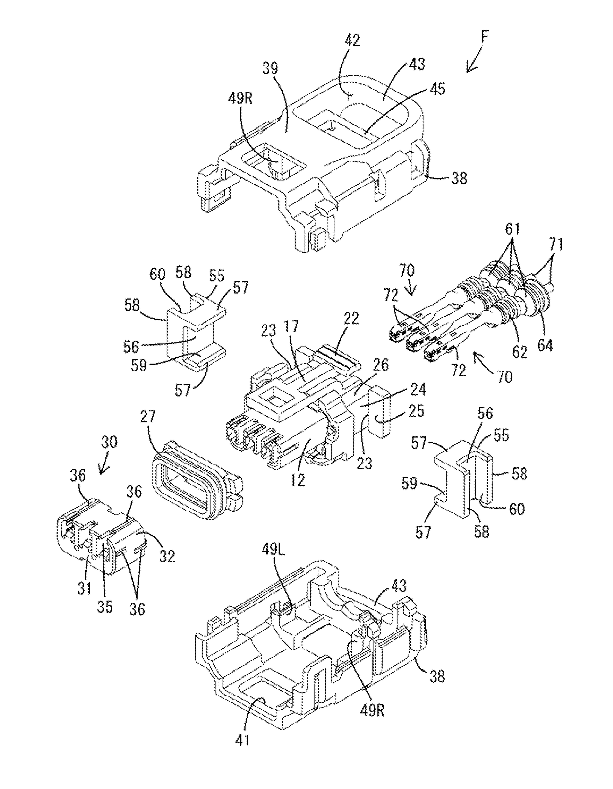
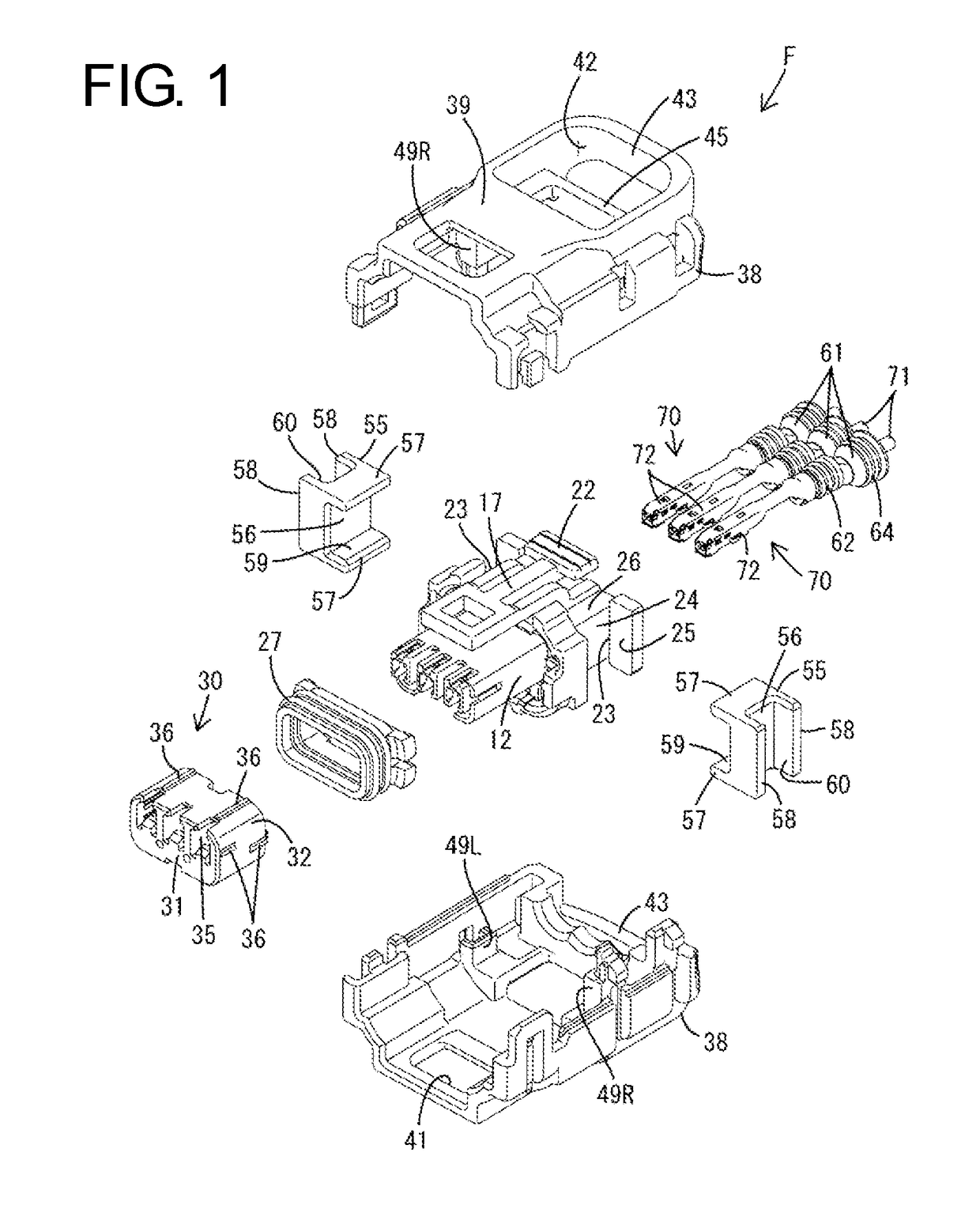
[0038]One specific embodiment of the invention is described with reference to FIGS. 1 to 21. Note that, in the following description, a left side in FIGS. 7, 9 to 12, 15 and 19, an oblique left lower side in FIGS. 1 to 4 and 21 and an oblique right upper side in FIGS. 8, 16 and 17 are defined as a front side concerning a front-back direction. Concerning a vertical direction, upper and lower sides shown in FIGS. 1 to 6, 8 to 10, 13 to 18, 20 and 21 are defined as upper and lower sides. A connector of this embodiment includes a male connector M and a female connector F connectable to and separable from each other.

[0039]As shown in FIGS. 9 and 10, the male connector M has a male housing 80 made e.g. of synthetic resin. The male housing 80 includes a terminal holding portion 81 and a receptacle 82 projecting in the same direction as a connecting direction to the female connector F (right in FIGS. 9 and 10) from the terminal holding portion 81. A lock projection 83 is formed on the upper...


PUM


Abstract

A connector (F) includes an inner housing (11). Terminal fittings (72) fixed to front end parts of wires (71) are inserted into the inner housing (11) from behind. An outer housing (37) is mounted relatively displaceably with respect to the inner housing (11) and is held out of contact with the terminal fittings (72). Two resilient positioning members (55) are configured to position the inner housing (11) and the outer housing (37) and spaced apart in a circumferential direction.

Description

BACKGROUND[0001]1. Field of the Invention[0002]The invention relates to a connector.[0003]2. Related Art[0004]Japanese Unexamined Patent Publication No. 2015-018617 discloses a connector in which a terminal-side housing carrier for accommodating and holding terminal fittings and a wire-side housing carrier for accommodating wires are coupled via a resilient portion. In this connector, if the wire vibrates, the terminal-side housing carrier and the wire-side housing carrier are displaced relatively while resiliently deforming the resilient portion and the vibration of the wire can be attenuated by this resilient deformation of the resilient portion.[0005]In the above-described connector, the resilient portion has a ring shape continuous over the entire circumference. Thus, a large amount of material is used to produce the resilient portion, thereby increasing material cost.[0006]The present invention was completed based on the above situation and aims to reduce cost.SUMMARY[0007]The ...

Claims


Application Information

Patent Timeline
Patent Type & Authority Patents(United States)
IPC IPC(8): H01R13/40H01R13/502H01R13/516H01R13/631H01R13/42H01R13/533
CPCH01R13/5025H01R13/42H01R13/6315H01R13/516H01R13/533
Inventor HASHIMOTO, YOUJIROUNAKAI, KAZUO
Owner SUMITOMO WIRING SYST LTD
Why Eureka
Try Eureka