Daylighting device
a daylighting and light source technology, applied in the direction of parallel plane units, lenses, synthetic resin layered products, etc., can solve the problem of unnecessary air-conditioning cost generation, and achieve the effect of providing a bright light environmen
- Summary
- Abstract
- Description
- Claims
- Application Information
AI Technical Summary
Benefits of technology
Problems solved by technology
Method used
Image

Examples
first embodiment
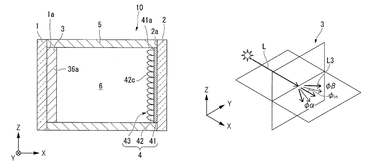
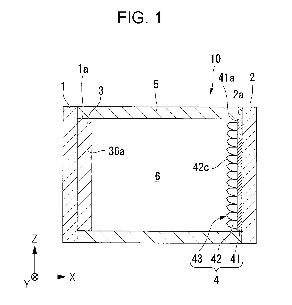
[0071]FIG. 1 is a cross-sectional view illustrating a configuration of a daylighting device that is a first embodiment of the present invention.
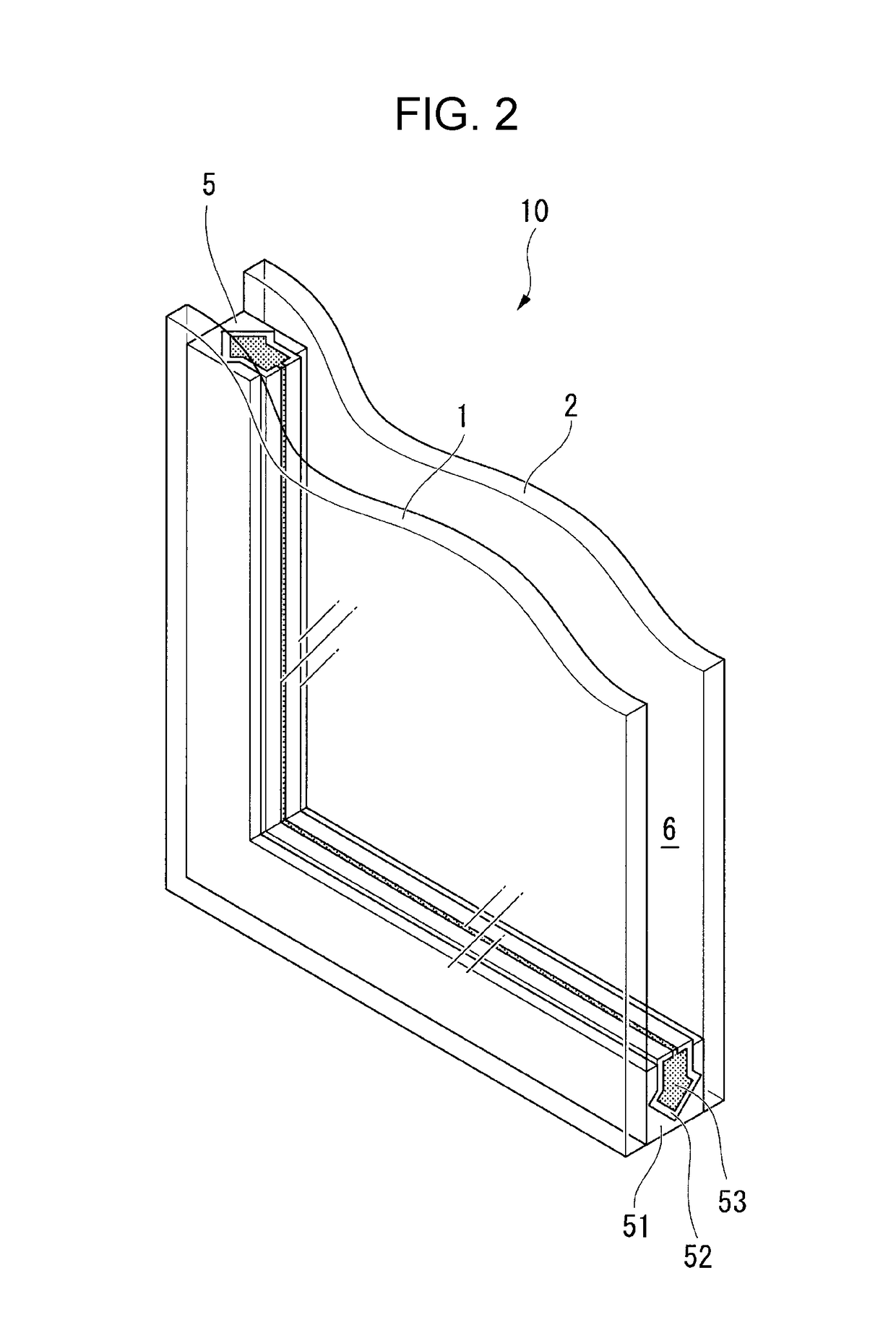
[0072]FIG. 2 is a perspective sectional view partially illustrating the configuration of the daylighting device.
[0073]FIG. 3 is perspective view illustrating a configuration of a light diffusion layer.
[0074]FIG. 4 is a diagram illustrating the light diffusion layer of a pseudo-stripe structure as the other form of the light diffusion layer.
[0075]FIG. 5 is a diagram illustrating a structure including a light diffusion particle as the other aspect of the light diffusion layer.
[0076]FIG. 6 is a perspective view illustrating a structure of a daylighting layer.
[0077]The daylighting device according to the present embodiment is, for example, an example of the daylighting device for collecting the solar light (external light) indoors in a state where the daylighting device is assembled to a window frame indoors.
[0078]As illustrated in FIG. 1, a day...
second embodiment
[0176]Next, a daylighting device according to second embodiment will be described.
[0177]A basic configuration of a daylighting device 20 of the present embodiment to be described below is the same as that of the first embodiment above and is different from the first embodiment in that a UV protecting film 7 and the plurality of light diffusion layers 3 are included.
[0178]Therefore, in the following description, the difference feature of the configuration will be described in detail and the description of common portions as the first embodiment above will not be described. In addition, in each drawing to be used in the description, the same reference numerals are allocated to the common configuration elements of FIGS. 1 to 9.
[0179]FIG. 19 is a cross-sectional view illustrating a schematic configuration of a daylighting device of a second embodiment.
[0180]As illustrated in FIG. 19, in the daylighting device 20 of the present embodiment, the light diffusion layer (first light diffusion...
third embodiment
[0190]Next, a daylighting device of third embodiment will be described.
[0191]A basic configuration of a daylighting device 30 of the present embodiment to be described below is the same as that of the first embodiment above and is different from the first embodiment in that the daylighting layer 4 and the light diffusion layer 3 are disposed on the second substrate 2 side. Therefore, in the following description, the difference feature of the configuration will be described in detail and the description of common portions as the first embodiment above will not be described. In addition, in each drawing to be used in the description, the same reference numerals are allocated to the common configuration elements of FIGS. 1 to 9.
[0192]FIG. 21 is a cross-sectional view illustrating a schematic configuration of a daylighting device of a third embodiment.
[0193]As illustrated in FIG. 21, in the daylighting device 30 of the present embodiment, the light diffusion layer 3 and the daylighting...
PUM
| Property | Measurement | Unit |
|---|---|---|
| angle | aaaaa | aaaaa |
| inner angles | aaaaa | aaaaa |
| incident angle | aaaaa | aaaaa |
Abstract
Description
Claims
Application Information
 - R&D Engineer
- R&D Manager
- IP Professional
- Industry Leading Data Capabilities
- Powerful AI technology
- Patent DNA Extraction
Browse by: Latest US Patents, China's latest patents, Technical Efficacy Thesaurus, Application Domain, Technology Topic.
© 2024 PatSnap. All rights reserved.Legal|Privacy policy|Modern Slavery Act Transparency Statement|Sitemap