Concrete i-beam for bridge construction

a technology of concrete ibeams and bridges, which is applied in bridges, bridge erection/assembly, and bridges. it can solve the problems of changing the strength of the beam, the inability to do post-cast inspection of the interior the small cracks and fractures of the box beam, so as to improve the accuracy and precision of the beam dimensions, and the risk of cracking is reduced

Active Publication Date: 2018-06-05
FLORIDA INTERNATIONAL UNIVERSITY
View PDF14 Cites 16 Cited by
  • Summary
  • Abstract
  • Description
  • Claims
  • Application Information

AI Technical Summary

Benefits of technology

[0011]UHPC has been used in bridge construction as a grout material. UHPC can also be advantageously used to connect beams of the subject invention. The use of UHPC as a grout material to connect both the top and bottom flanges between two beams can minimize the risk of cracking in the deck where the flan...

Problems solved by technology

Because the foam core fills the central space of the box beam and is surrounded by concrete after the pour, it is not possible to do a post-cast inspection of the interior of the box-beam.
It is also possible for the foam core to shift during the pour causing inconsistencies in concrete thickness in the webs and flanges, which change the strength of the ...

Method used


Image

  • Concrete i-beam for bridge construction
  • Concrete i-beam for bridge construction
  • Concrete i-beam for bridge construction

Examples


Embodiment Construction

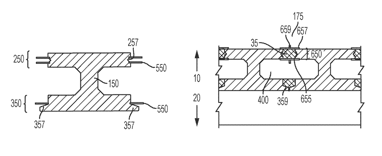
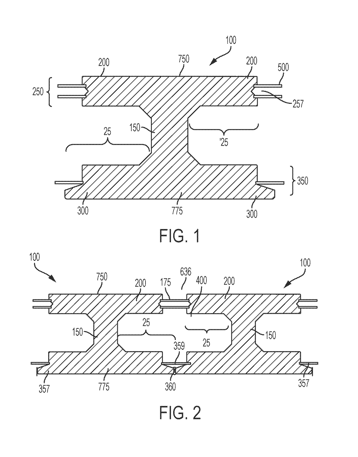
[0026]The subject invention provides methods and devices for casting and joining beams that can be used to build structures, particularly short- and mid-span bridges. More specifically, the subject invention provides one or more beam embodiments with flanges. The beams can be placed adjacent to each other and joined at the flanges to form a superstructure. Alternatively, other structures or components, such as pre-cast panels, can be placed on, and joined to, the beams to create a superstructure.

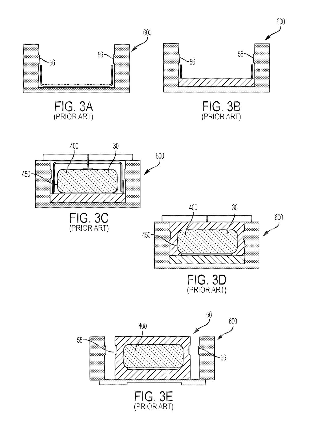
[0027]The structure of the joined beams can be used similarly to standard box beams. Advantageously, the joined beams can provide an interior void, like a box beam, but that is not filled with a foam core and allows for full post-cast inspection, unlike standard box beams. Grout material, such as, for example, ultra-high performance concrete (UHPC) can be used to join the beams to minimize cracking and separation.

[0028]The subject invention is particularly useful in the field of bridge const...


PUM


Abstract

A beam used for construction, particularly of short- to mid-span bridges. A beam can include flanges extending from a web that are joined to flanges of another beam. When joined two beams form an open internal void. The beams can be manufactured from concrete and include an embedded reinforcement cage. Manufacture of the beams utilizes a formwork that can be filled in a single pour.

Description

BACKGROUND OF INVENTION[0001]Pre-stressed concrete box-beams have been used since the 1950's to build short and medium span bridges. It is estimated that there are approximately 54,000 box beam bridges in service in the United States. Box-beams are popular because they can be used in multiple ways to quickly and safely construct bridges.[0002]Box beams are typically manufactured by casting reinforced concrete around a foam core in a mold or formwork. Rebar is used to build a reinforcing “cage” around the foam core prior to pouring the concrete. The bottom part of the cage is placed first and then a layer of concrete is poured. The foam core is placed on the layer of concrete and the top of the cage is built up around the foam core. Concrete is poured to surround the foam core and the rest of the cage.[0003]Because the foam core fills the central space of the box beam and is surrounded by concrete after the pour, it is not possible to do a post-cast inspection of the interior of the ...

Claims


Application Information

Patent Timeline
IPC IPC(8): E04B5/06E01D2/02E01D21/00E04G13/04E01D101/26
CPCE04B5/06E01D2/02E01D21/00E04G13/04E01D2101/26E01D2/00E04G15/068
Inventor GARBER, DAVID
Owner FLORIDA INTERNATIONAL UNIVERSITY
Why Eureka
Try Eureka