Optical disk drive and methods for counting the number of tracks on an optical disk

Inactive Publication Date: 2000-09-12
MEDIATEK INC
View PDF8 Cites 11 Cited by
  • Summary
  • Abstract
  • Description
  • Claims
  • Application Information

AI Technical Summary

Benefits of technology

The invention is a positive peak level comparator for generating a positive peak pulse when a TES (Tracking Error Signal) is higher than a predetermined positive level, a negative peak level comparator for generating a negative peak pulse when the TES is lower than a predetermined negative level, and a logic circuit for generating an output pulse when said positive peak pulse and said negative peak pulse have been alternately input thereto. The arrangement prevents the TES from being miscounted even if the TES is disturbed due to the occurrence of, for example, a noise at a level close to either said predetermined positive level or said predetermined negative level and either said peak pulse or said negative pulse is successively generated.
comparator, respectively, during a low-velocity seek operation, and for generating an output pulse when said positive peak pulse and said negative peak pulse have been alternately input from said second positive peak level comparator and said second negative peak level comparator, respectively, during a high-velocity seek operation, to prevent the TES from being miscounted by the decrease of the amplitude of TES which is apt to be caused if a laser beam crosses a defect portion on the disk during a high-velocity seek operation.
The invention also includes a window comparator for generating a zero cross pulse when said tracking error signal is within a predetermined range including a zero level, a positive peak level comparator for generating a positive peak pulse when said tracking error signal is higher than a predetermined positive level, a negative peak level comparator for generating a negative peak pulse when said tracking error signal is lower than a predetermined negative level, and a logic circuit for generating an output pulse when said zero cross pulse, said positive peak pulse, and said negative peak pulse have been input in predetermined order, to prevent the TES from being miscounted even if the TES is disturbed by the occurrence of, for example, a noise at a level close to either said predetermined positive level or said predetermined negative level and either said peak pulse or said negative pulse is successively generated, or the TES is disturbed for the reason why said predetermined range including the zero level is exceeded. The invention also includes a window comparator for generating a zero cross pulse when said tracking error signal is within a predetermined range including a zero level, a positive peak level comparator for generating a positive peak pulse when said tracking error signal is higher then a predetermined positive level, a negative peak level comparator for generating a negative peak pulse when said tracking error signal is lower than a predetermined negative level, and a logic circuit for generating an output pulse when said positive peak pulse and said negative peak pulse have been alternately input from said positive peak level comparator and said negative peak level comparator, respectively, during a low-velocity seek operation and generating an output pulse when a zero cross pulse has been input from said window comparator during a high-velocity seek operation, to eliminate the effect of a noise caused by a defect portion, etc. with no use of said window comparator for generating said zero cross pulse if a seek operation is performed at a low velocity.
The invention also includes a window comparator for generating a zero cross pulse when said tracking error signal is within a predetermined range including a zero level, a filter circuit for passing said tracking error signal of high frequency with high gain and, on the other hand, passing said tracking error signal of low frequency with low gain, a positive peak level comparator for generating a positive peak pulse when an output signal from said filter circuit is higher than a predetermined positive level, a negative peak level comparator for generating a negative peak pulse when an output signal from said filter circuit is lower than a predetermined negative level, and a logic circuit for generating an output pulse when said zero cross pulse, said positive peak pulse, and said negative peak pulse have been input in predetermined order, to relatively amplify the amplitude of TES in said filter circuit so as to decrease the effect of the decrease of the amplitude of TES which is apt to extend during a high-velocity seek operation.

Problems solved by technology

When such noise is caused, the above conventional circuit structure is apt to err in counting the number of tracks.
Said noise thus generated causes a pulse and frequently count errors in counting the number of tracks by the track count logic 133.
The same problem is also caused if a laser beam passes through a pre-pitted portion.
Further, other noises are apt to cause counting errors.

Method used


Image

  • Optical disk drive and methods for counting the number of tracks on an optical disk
  • Optical disk drive and methods for counting the number of tracks on an optical disk
  • Optical disk drive and methods for counting the number of tracks on an optical disk

Examples


Embodiment Construction

Referring now more particularly to the drawing, like numerals denote like features and structural elements in the various figures.

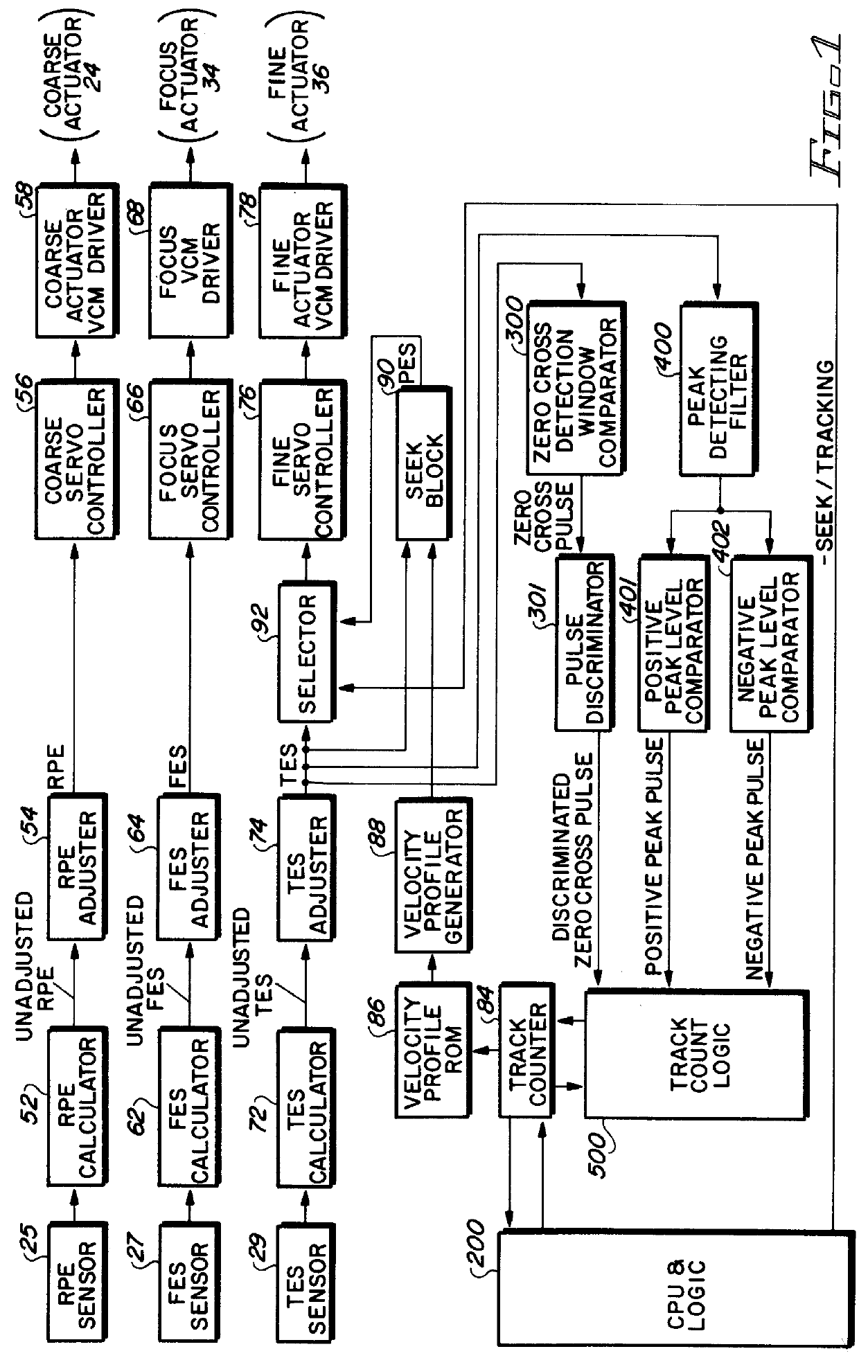
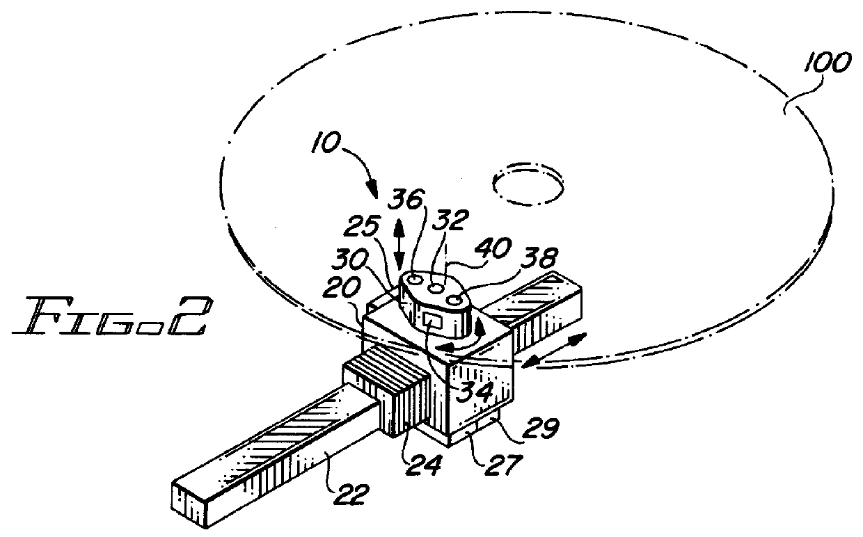
FIG. 2 shows a part of an embodiment of an optical disk drive according to the invention. In the figure, an optical head 10 is composed of a coarse actuator 20 and a fine actuator 30. The coarse actuator 20 is supported by a rail 22 so that it can move freely in the radial direction of an optical disk 100 (in the direction of a seek operation), and is driven in the direction of the seek operation by a coarse actuator VCM (Voice Coil Motor) 24.

The fine actuator 30 is supported by the coarse actuator 20 through a shaft 32 so that it can move in the focusing and tracking directions and is driven in the focusing direction and in the tracking direction by a focus VCM 34 and a tracking VCM 36, respectively. The fine actuator 30 has a fixed objective lens 38 which a laser beam 40 is projected onto optical disk 100.

Also, coarse actuator 20 is provided with a rela...


PUM


Abstract

The invention is a positive peak level comparator for generating a positive peak pulse when a TES (Tracking Error Signal) is higher than a predetermined positive level, a negative peak level comparator for generating a negative peak pulse when the TES is lower than a predetermined negative level, and a logic circuit for generating an output pulse when said positive peak pulse and said negative peak pulse have been alternately input thereto. The arrangement prevents the TES from being miscounted even if the TES is distrubed due to the occurrence of, for example, a noise at a level close to either said predetermined positive level or said predetermined negative level and either said peak pulse or said negative pulse is successively generated.

Description

BACKGROUND OF THE INVENTION1. Field of the InventionThis invention relates to an optical disk drive, and is particularly concerned with a method for counting the number of tracks an optical head crosses during a seek operation in an optical disk drive.2. Description of the Related ArtIn an optical disk drive seek operation in which a laser beam (or an optical head) moves from a current position to a target position (or a target track) over the tracks, it is necessary to count the number of tracks the laser beam crosses during the seek operation, based on a TES (Tracking Error Signal), to obtain positional information of the moving optical head.Optical structures to generate a TES are grouped into several classes, such as a push-pull method, a three-beam method, etc. However, a TES in any method, is a signal of a waveform showing that a positive peak and a negative peak occur alternately each time a laser beam crosses a land part 110 and a groove part 120 of an optical disk 100, as s...

Claims


Application Information

Patent Timeline
IPC IPC(8): G11B7/00
CPCG11B7/08541G11B7/0948
Inventor KAGAMI, NAOYUKIKUBO, HIROAKIOKADA, KEIICHI
Owner MEDIATEK INC
Why Eureka
Try Eureka