Multilayer balanced filter

Active Publication Date: 2011-07-14
MURATA MFG CO LTD
View PDF7 Cites 13 Cited by
  • Summary
  • Abstract
  • Description
  • Claims
  • Application Information

AI Technical Summary

Benefits of technology

[0011]Preferred embodiments of the present invention solve the above problems and provide a multilayer balanced filter whose size can be easily reduced and which can realize specified impedance conversion between the input and output thereof.

Problems solved by technology

In this case, impedance conversion is required between the unbalanced terminal and the balanced terminals.
However, the structure described in Japanese Unexamined Patent Application Publication No. 2005-45447 does not allow for easy design and adjustment for appropriate impedance conversion between these two types of terminals.

Method used


Image

  • Multilayer balanced filter
  • Multilayer balanced filter
  • Multilayer balanced filter

Examples


first preferred embodiment

[0040]A multilayer balanced filter according to a first preferred embodiment will be described with reference to FIGS. 2 to 7D.

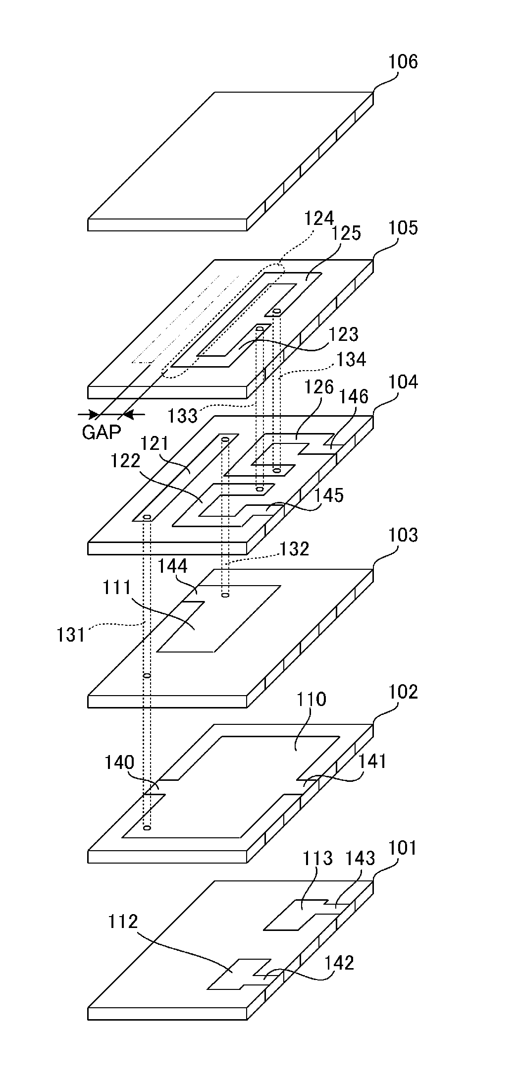
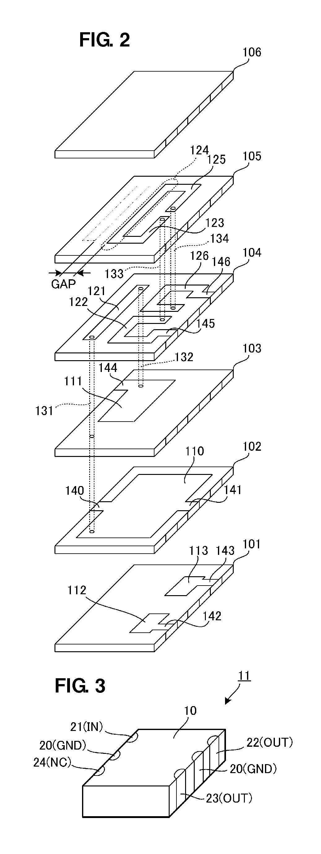
[0041]FIG. 2 is an exploded perspective view of the multilayer balanced filter according to the first preferred embodiment, and FIG. 3 is an external perspective view thereof.

[0042]Referring to FIG. 2, this multilayer balanced filter is preferably configured as a stack including a plurality of dielectric layers 101 to 106 each having predetermined electrode patterns provided thereon. Hence, this stack is constituted by a stack including dielectric layers and electrode layers.

[0043]A dielectric layer 103 includes a first capacitor electrode 111 provided thereon. The first capacitor electrode 111 extends to the left side of the dielectric layer 103 via an extension electrode 144. A dielectric layer 102 includes a ground electrode 110 provided thereon. The ground electrode 110 extends to the left and right sides of the dielectric layer 102 respectively via exte...

second preferred embodiment

[0080]A multilayer balanced filter according to a second preferred embodiment will be described with reference to FIGS. 8 to 10.

[0081]FIG. 8 is an exploded perspective view of the multilayer balanced filter according to the second preferred embodiment, and FIG. 9 is an external perspective view thereof. The differences from the first preferred embodiment illustrated in FIG. 2 are the configurations of dielectric layers 101, 102, and 105.

[0082]Referring to FIG. 8, this multilayer balanced filter is configured as a stack including a plurality of dielectric layers 101 to 106 each having predetermined electrode patterns provided thereon. Hence, this stack is constituted by a stack including dielectric layers and electrode layers.

[0083]The dielectric layer 103 includes a first capacitor electrode 111 provided thereon. The first capacitor electrode 111 extends to the left side of the dielectric layer 103 via an extension electrode 144. The dielectric layer 102 includes a ground electrode ...

third preferred embodiment

[0091]A multilayer balanced filter according to a third preferred embodiment will be described with reference to FIGS. 11 and 12.

[0092]FIG. 11 is an exploded perspective view of the multilayer balanced filter according to the third preferred embodiment, and FIG. 12 is an equivalent circuit diagram thereof. The difference from the multilayer balanced filter of the second preferred embodiment illustrated in FIG. 8 is that a dielectric layer 107 is provided between a dielectric layer 103 and a dielectric layer 104.

[0093]The dielectric layer 103 includes a first capacitor electrode 111 and a fifth capacitor electrode 115 provided thereon. The fifth capacitor electrode 115 extends to the left side of the dielectric layer 103 via an extension electrode 144. A dielectric layer 102 includes a ground electrode 110 provided thereon. The ground electrode 110 extends to the right side of the dielectric layer 102 via an extension electrode 141. A dielectric layer 101 includes a second capacitor ...


PUM


Abstract

A multilayer balanced filter includes a first coil including a first straight line electrode and via electrodes. A first capacitor, a second capacitor, and a third capacitor are provided respectively between a ground electrode and a first capacitor electrode, between the ground electrode and a second capacitor electrode, and between the ground electrode and a third capacitor electrode. The first coil and the first capacitor constitute an LC resonator. A second straight line electrode is arranged in parallel or substantially in parallel with the first straight line electrode, and a second coil and a third coil, each having a loop plane perpendicular or substantially perpendicular to the loop plane of the first coil, are provided. A second capacitor and a third capacitor are respectively connected between balanced output terminals and the ground.

Description

BACKGROUND OF THE INVENTION[0001]1. Field of the Invention[0002]The present invention relates to a multilayer balanced filter including a stack including a plurality of dielectric layers and electrode layers.[0003]2. Description of the Related Art[0004]A typical conventional band pass filter whose size and cost can be easily reduced is formed by providing a plurality of LC resonance circuits within a stack including dielectric layers and electrode layers.[0005]Such a multilayer band pass filter is disclosed in Japanese Unexamined Patent Application Publication No. 2005-45447.[0006]The configuration of a multilayer band pass filter disclosed in Japanese Unexamined Patent Application Publication No. 2005-45447 is described with reference to FIG. 1.[0007]FIG. 1 is a circuit diagram of the multilayer band pass filter disclosed in Japanese Unexamined Patent Application Publication No. 2005-45447. The multilayer band pass filter 1 includes an unbalanced input terminal 2, balanced output t...

Claims


Application Information

Patent Timeline
IPC IPC(8): H03H7/42
CPCH03H7/0115H03H7/09H03H2001/0085H03H7/422H03H7/1775
Inventor TANIGUCHI, TETSUO
Owner MURATA MFG CO LTD
Why Eureka
Try Eureka