Liquid discharge apparatus

Active Publication Date: 2017-02-16
SEIKO EPSON CORP
View PDF2 Cites 2 Cited by
  • Summary
  • Abstract
  • Description
  • Claims
  • Application Information

AI Technical Summary

Benefits of technology

The invention provides a liquid discharge apparatus that can adjust the discharge characteristic of liquid based on its remaining quantity in the container, the measurement consumption quantity, and the estimated consumption quantity. By comparing the measurement consumption quantity with the estimated consumption quantity, the apparatus can inspect for any discharge defects and adjust the amplitude of the drive signal accordingly. This allows for a more accurate discharge characteristic, reducing errors in the discharge speed and rate. The apparatus can also adjust the amplitude of the drive signal based on the comparison between the measurement consumption quantity and the estimated consumption quantity after the recovery operation is performed. Additionally, the apparatus can determine whether the liquid is added to the container and adjust the amplitude of the drive signal accordingly to ensure a suitable discharge characteristic regardless of the viscosity of the liquid.

Problems solved by technology

However, in reality, for example, a discharge defect in which liquid is not discharged from a nozzle may occur.
In a situation in which such a discharge defect has occurred, there is a problem with the technique in JP-A-2007-160671 in that it is not possible to suitably correct the voltage of the drive signal.

Method used


Image

  • Liquid discharge apparatus
  • Liquid discharge apparatus
  • Liquid discharge apparatus

Examples


first embodiment

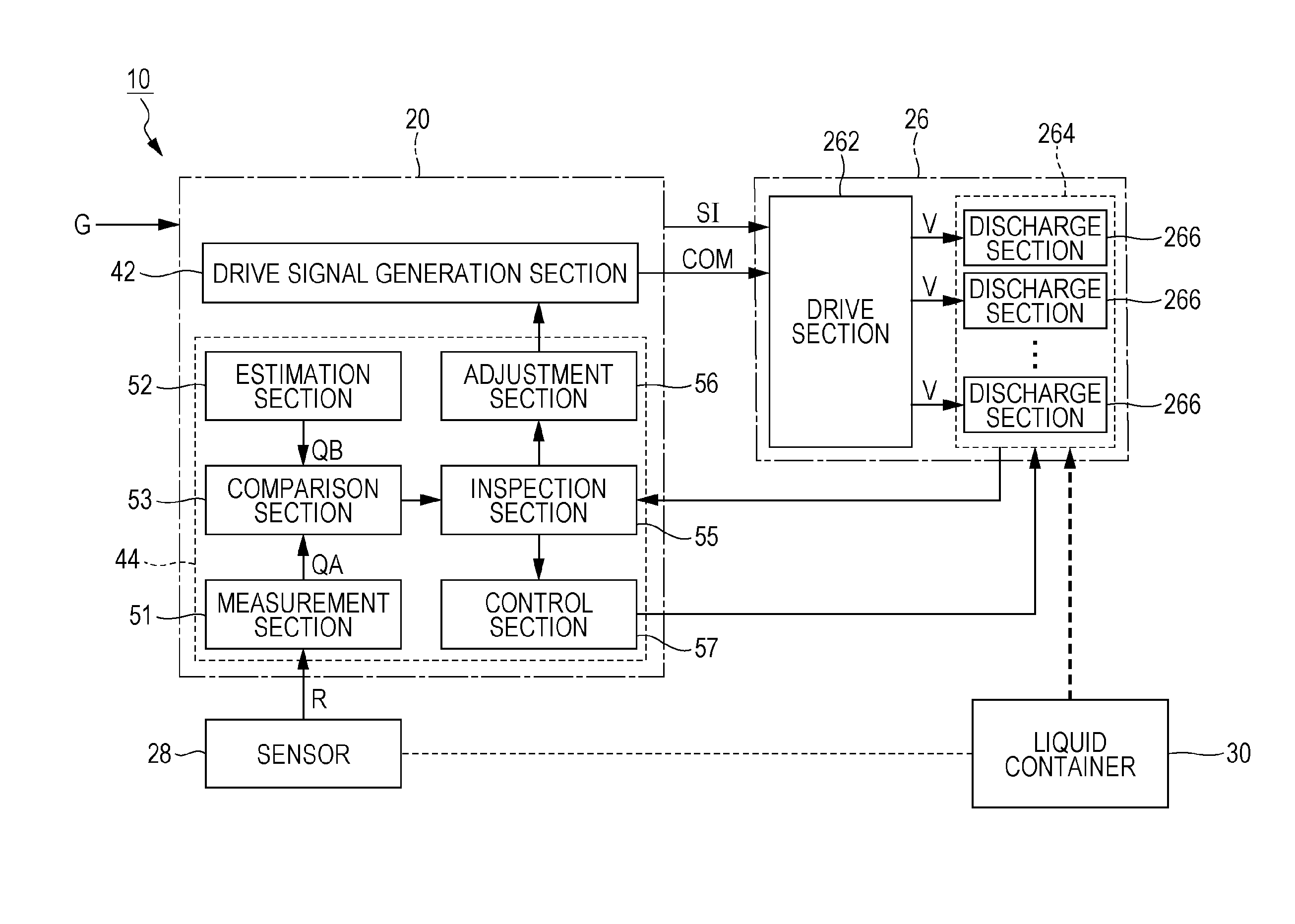
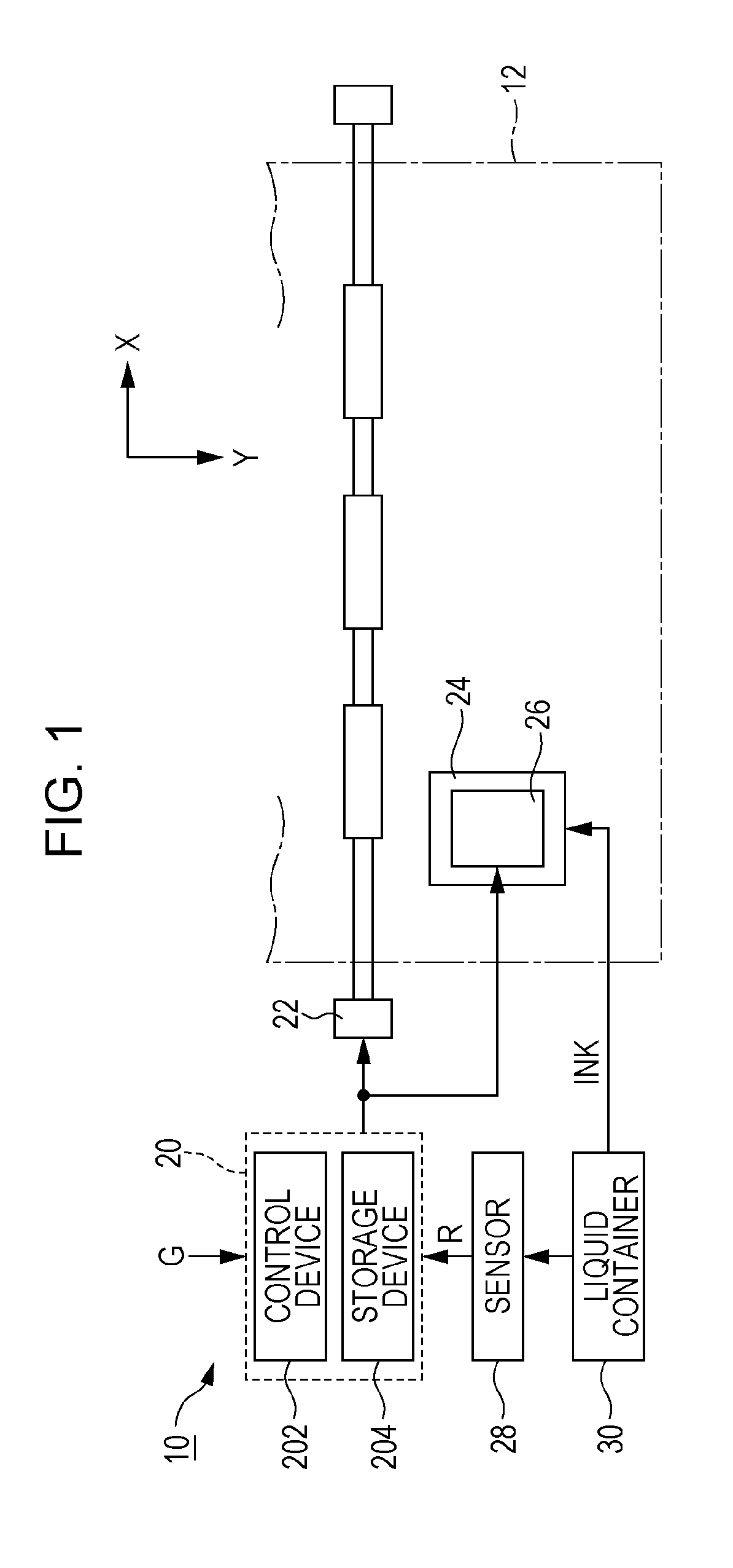
[0024]FIG. 1 is a partial configuration diagram of a liquid discharge apparatus 10 according to a first embodiment of the invention. The liquid discharge apparatus 10 according to the first embodiment is an ink jet printer that discharges ink, which is an example of liquid, onto a medium 12, such as printing paper, or the like. As illustrated in FIG. 1, the liquid discharge apparatus 10 includes a control unit 20, a transport mechanism 22, a carriage 24, a liquid discharge unit 26, a sensor 28, and a liquid container 30. The liquid container 30 is a container (ink tank) that stores ink. In reality, a plurality of colors of ink is stored in the liquid container 30. However, in the following description, attention is focused on one kind of ink for the sake of convenience. The liquid discharge apparatus 10 according to the first embodiment is a continuous ink supply system (CISS) printer capable of replenishing the liquid container 30 with ink later. However, it is also possible to use...

second embodiment

[0057]In the following, a description will be given of a second embodiment of the invention. In this regard, in the following each mode, a symbol used in the description of the first embodiment is given to an element having the same actions and functions as those of the first embodiment, and a detailed description of each element will be suitably omitted.

[0058]FIG. 9 is a functional configuration diagram of a liquid discharge apparatus 10 according to the second embodiment. As is understood from FIG. 9, the liquid discharge apparatus 10 according to the second embodiment has a configuration in which a range control section 58 is added to the liquid discharge apparatus 10 according to the first embodiment. The range control section 58 variably sets the permissible range P (the upper limit value p1 and the lower limit value p2).

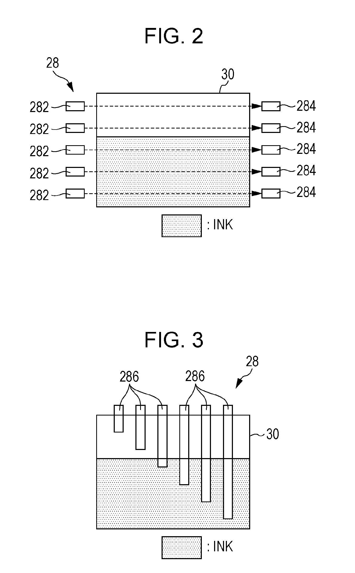
[0059]It is possible to replenish the liquid container 30 with low-viscosity or high-viscosity non-regular ink in addition to regular ink having a predetermine...


PUM


Abstract

A liquid discharge apparatus includes: a liquid discharge section configured to discharge liquid supplied from a liquid container in accordance with a drive signal; a sensor configured to measure a remaining quantity of the liquid in the liquid container; a measurement section configured to identify a measurement consumption quantity being a variation quantity of the remaining quantity in a measurement period; an estimation section configured to estimate an estimated consumption quantity of the liquid in accordance with print contents in the measurement period; a comparison section configured to make a comparison between the measurement consumption quantity and the estimated consumption quantity; if the measurement consumption quantity is smaller than the estimated consumption quantity by comparison of the comparison section, an inspection section configured to inspect whether or not there is a discharge defect in the liquid discharge section; and if the inspection section determines that there are no discharge defects, an adjustment section configured to adjust an amplitude of the drive signal.

Description

BACKGROUND[0001]1. Technical Field[0002]The present invention relates to a technique for discharging liquid, such as ink.[0003]2. Related Art[0004]To date, liquid discharge apparatuses that discharge liquid, such as ink, or the like from a nozzle by the supply of a drive signal have been proposed. For example, JP-A-2007-160671 discloses a printer in which the voltage of a drive signal is corrected in accordance with the difference between the amplitude of a detection signal indicating a change in the electric field when liquid is discharged to a droplet receiving section (cap) and a predetermined reference amplitude.[0005]In the technique in JP-A-2007-160671, it is necessary to have a change in the electric field when liquid is actually discharged to a droplet receiving section in order to generate a detection signal or correct a drive signal. However, in reality, for example, a discharge defect in which liquid is not discharged from a nozzle may occur. In a situation in which such ...

Claims


Application Information

Patent Timeline
IPC IPC(8): B41J2/175
CPCB41J2002/17569B41J2/0451B41J2/16579B41J2/04588B41J2/0456B41J2/17566B41J2/165B41J2/04581B41J29/393B41J2002/17589B41J2/0459B41J2/16526B41J2/04508B41J2/04573B41J2/175B41J2002/17573
Inventor MUNAKATA, MANABU
Owner SEIKO EPSON CORP
Why Eureka
Try Eureka