Direct measurement of the b0-off-resonance field during magnetic resonance fingerprinting

Active Publication Date: 2019-08-08
KONINKLJIJKE PHILIPS NV
View PDF0 Cites 5 Cited by
  • Summary
  • Abstract
  • Description
  • Claims
  • Application Information

AI Technical Summary

Benefits of technology

The invention provides a better way to determine a magnetic field during MR fingerprinting. Instead of using a dictionary, the magnetic field is measured directly. This allows for more accurate mapping of the B0-off-resonance magnetic field. The invention also analyzes multiple signals during a single pulse repetition, which can help to reduce noise in the magnetic field map. The magnetic resonance fingerprinting dictionary is also influenced by the transmit B1 magnetic field magnitude, which can make the calculations more accurate. Overall, the invention improves the accuracy and reliability of MR fingerprinting.

Problems solved by technology

However, non-uniformities in the B0 magnetic field can be caused by a variety of factors.

Method used


Image

  • Direct measurement of the b0-off-resonance field during magnetic resonance fingerprinting
  • Direct measurement of the b0-off-resonance field during magnetic resonance fingerprinting
  • Direct measurement of the b0-off-resonance field during magnetic resonance fingerprinting

Examples


Embodiment Construction

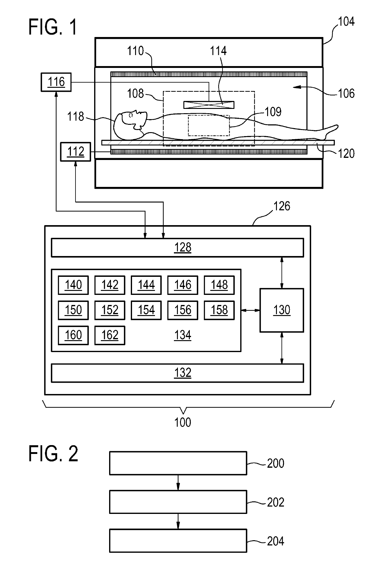
[0062]Like numbered elements in these Figs are either equivalent elements or perform the same function. Elements which have been discussed previously will not necessarily be discussed in later Figs if the function is equivalent.

[0063]FIG. 1 shows an example of a magnetic resonance imaging system 100 with a magnet 104. The magnet 104 is a superconducting cylindrical type magnet with a bore 106 through it. The use of different types of magnets is also possible; for instance it is also possible to use both a split cylindrical magnet and a so called open magnet. A split cylindrical magnet is similar to a standard cylindrical magnet, except that the cryostat has been split into two sections to allow access to the iso-plane of the magnet, such magnets may for instance be used in conjunction with charged particle beam therapy. An open magnet has two magnet sections, one above the other with a space in-between that is large enough to receive a subject: the arrangement of the two sections ar...


PUM


Abstract

The invention provides for a magnetic resonance imaging system (100). Machine executable instructions cause a processor controlling the MRI system to control (200) the magnetic resonance imaging system with the pulse sequence commands to acquire the magnetic resonance data. The pulse sequence commands are configured for controlling the magnetic resonance imaging system to acquire the magnetic resonance data according to a magnetic resonance fingerprinting protocol. The pulse sequence commands are configured for controlling the magnetic resonance imaging system to acquire the magnetic resonance data during multiple pulse repetitions (302). The pulse sequence commands are configured for controlling the magnetic resonance imaging system to cause gradient induced spin rephasing at least twice during each of the multiple pulse repetitions using a gradient magnetic field generating system (110, 112). The pulse sequence commands are configured for controlling the magnetic resonance imaging system to acquire at least two magnetic resonance signals during each of the multiple pulse repetitions. Each of the at least two magnetic resonance signals is measured during a separate one of the gradient induced spin rephasing. The magnetic resonance data comprises the at least two magnetic resonance signals acquired during each of the multiple pulse repetitions. Execution of the machine executable instructions further cause the processor to calculate (202) a B0-off-resonance map (158) using the magnetic resonance data, wherein the B0-off-resonance map is descriptive of a B0-off-resonance magnetic field of the magnetic resonance imaging system when the subject is within the imaging zone, wherein the B0-off-resonance map is at least partially calculated using at least two magnetic resonance signals measured during a single pulse repetition. Execution of the machine executable instructions further cause the processor to generate (204) at least one magnetic resonance parametric map by comparing the magnetic resonance data with a magnetic resonance fingerprinting dictionary (152).

Description

FIELD OF THE INVENTION[0001]The invention relates to magnetic resonance imaging, in particular to magnetic resonance fingerprinting techniques.BACKGROUND OF THE INVENTION[0002]Magnetic Resonance (MR) fingerprinting is a technique where a number of RF pulses often associated with appropriate gradient switching, distributed in time, are applied such that they cause signals from different materials or tissues to have a unique contribution to the measured MR signal. A dictionary of precalculated signal contributions from a large set or a fixed number of substances is compared to the measured MR signals within each single voxel. Furthermore, also the composition within each voxel can further be determined. For example if it is known that a voxel only contains gray matter, white matter, CSF, or fat the contribution from these three materials need only be considered to accurately determine the composition of the voxel. If a larger dictionary with higher resolution is used, MR fingerprintin...

Claims


Application Information

Patent Timeline
IPC IPC(8): G01R33/44G01R33/24G01R33/56
CPCG01R33/443G01R33/243G01R33/246G01R33/5608G01R33/50
Inventor MEINEKE, JAN JAKOBAMTHOR, THOMAS ERIKKOKEN, PETERSOMMER, KARSTEN
Owner KONINKLJIJKE PHILIPS NV
Why Eureka
Try Eureka