
Rectifier with quick disjunction inductive load

A rectifier and effect tube technology, applied in the field of breaking rectifiers

Inactive Publication Date: 2009-07-15
天津永恒泰科技有限公司
View PDF4 Cites 0 Cited by
  • Summary
  • Abstract
  • Description
  • Claims
  • Application Information

AI Technical Summary

Problems solved by technology

However, in some practical applications, when the input side of the rectifier is required to be disconnected, the inductive load is also demagnetized quickly

Method used


Image

  • Rectifier with quick disjunction inductive load
  • Rectifier with quick disjunction inductive load

Examples


Embodiment Construction

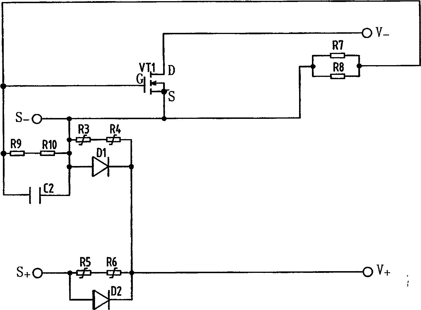
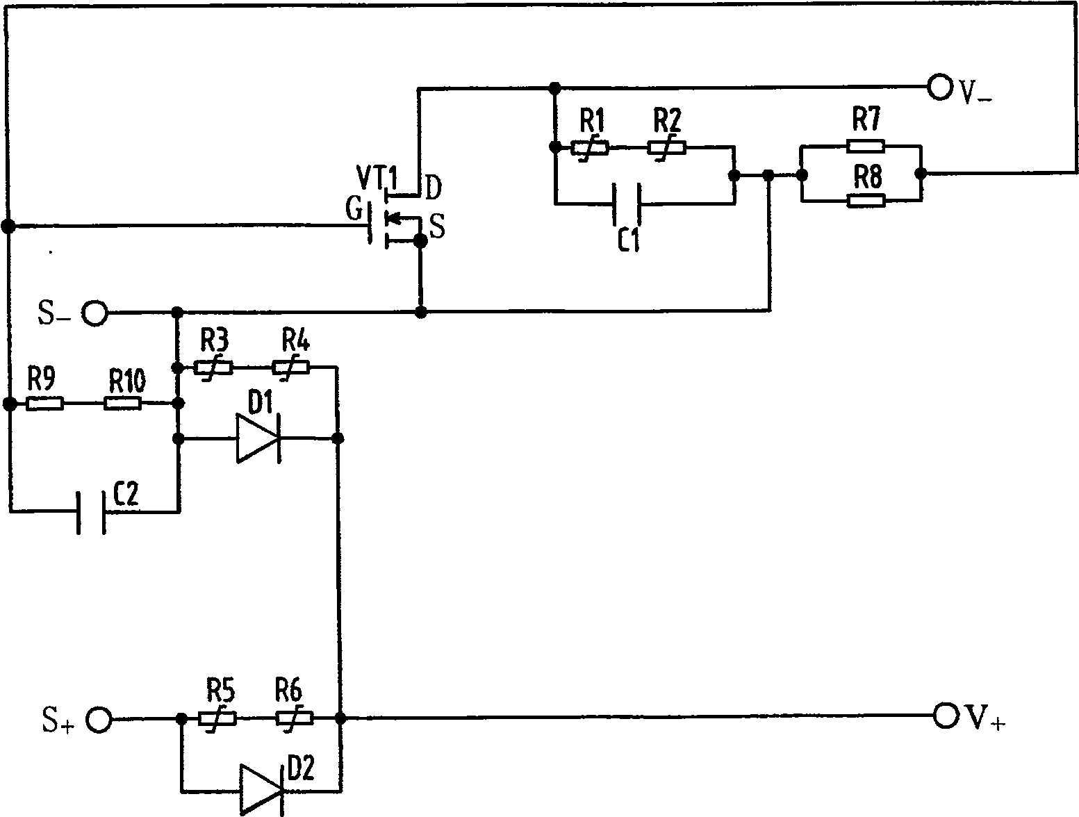
[0009] Specific embodiments are given below in conjunction with the accompanying drawings to further illustrate the breaking rectifier using field effect transistors as built-in switches of the present invention.

[0010] Such as figure 1 As shown, the breaking rectifier of the present invention using a field effect transistor as a built-in switch has a shunt resistance formed by connecting the fifth varistor R5 and the sixth varistor R6 in series and the second diode D2 in parallel. The first rectification unit, the positive terminal of the first rectification unit is connected to the positive pole S of the input power supply + , the negative terminal constitutes the positive output terminal V of the rectifier + ; A second rectifier unit formed by connecting a shunt resistance formed in series with a third varistor R3 and a fourth varistor R4 in parallel with the first diode D1 is also provided, and the negative terminal of the second rectifier unit is connected to The posi...


PUM


Abstract

A breaking rectifier using a field effect transistor as a built-in switch. It has a rectifying unit composed of a shunt resistance formed by two varistors in series and a diode connected in parallel. One end of the rectifying unit is connected to the positive pole of the input power supply, and the other end constitutes the positive output end of the rectifier. There is also a rectifier unit formed by connecting a shunt resistor in series with two varistors and a diode in parallel, one end of the rectifier unit is connected to the positive output terminal of the rectifier, and the other end is connected to the negative pole of the input power supply; the negative pole of the input power supply is also connected to a resistor and One capacitor, the other end of the resistor is connected to the gate of the field effect transistor through another resistor, and the other end of the capacitor is connected to the gate of the field effect transistor; the negative pole of the input power supply is also connected to the source of the field effect transistor; the gate of the field effect transistor They are respectively connected to the source through two resistors, and the drain of the FET is the negative pole of the output terminal of the rectifier. In the present invention, when the input is disconnected, the field effect tube is disconnected, the output side of the rectifier and the load cannot form a loop, and the inductive load can also be quickly demagnetized.

Description

technical field [0001] The invention relates to a rectifier. In particular, it relates to a breaking rectifier using a field effect transistor as a built-in switch, which can quickly demagnetize an inductive load when the power supply at the input side of the rectifier is disconnected. Background technique [0002] At present, the general-purpose rectifier is connected to the load on the output side. When the rectifier is working, the inductive load is working. Eliminates magnetic fields from inductive loads due to their characteristics. However, in some practical applications, when the input side of the rectifier is required to be disconnected, the inductive load is also demagnetized rapidly. Contents of the invention [0003] The technical problem to be solved by the present invention is to provide a breaking rectifier using a field effect transistor as a built-in switch that can quickly degauss the inductive load when the power supply at the input side of the rectifie...

Claims


Application Information

Patent Timeline
Patent Type & Authority Patents(China)
IPC IPC(8): H02H7/125
Inventor 陈立铭
Owner 天津永恒泰科技有限公司
Learn More