
Hardware driver and recording method

A technology of hard disk drives and recording methods, which is applied to the recording of information on magnetic disks, magnetic recording heads, bridge parts, etc., and can solve problems such as direction reversal delays

Inactive Publication Date: 2006-07-19
HITACHI GLOBAL STORAGE TECH NETHERLANDS BV
View PDF2 Cites 2 Cited by
  • Summary
  • Abstract
  • Description
  • Claims
  • Application Information

AI Technical Summary

Problems solved by technology

However, this direction reversal is delayed by the inductive component of the write head
Therefore, the current change waveform becomes gentle

Method used


Image

  • Hardware driver and recording method
  • Hardware driver and recording method
  • Hardware driver and recording method

Examples


no. 1 example

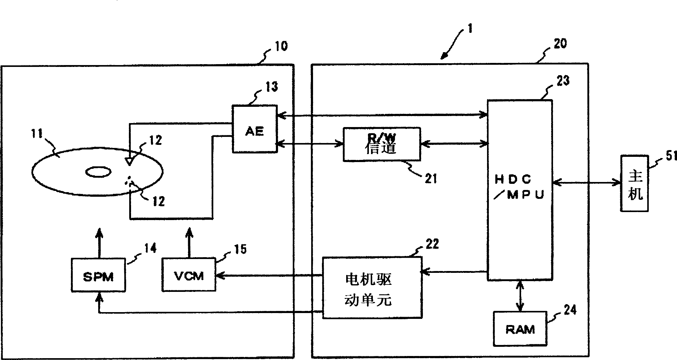
[0061] A first embodiment of the present invention will be described in detail below with reference to the accompanying drawings. In order to facilitate understanding of the present invention, the general structure of a hard disk drive (HDD) as an example of a recording medium drive will first be outlined. figure 1 is a block diagram schematically showing the structure of the HDD1 according to the present embodiment. The HDD 1 includes: a magnetic disk 11, which is a typical recording medium; a magnetic head element section 12, which is a typical magnetic head; arm electronics (arm electronics or AE) 13; a spindle motor (SPM) 14; a voice coil motor (VCM) 15 . These components are housed in a sealed enclosure 10 .

[0062] The HDD 1 includes a circuit board 20 which is fixed on the outer surface of the package case 10 . Mounted on the circuit board 20 are: a read / write channel (R / W channel) 21; a motor driver unit 22; an integrated circuit 23 including a hard disk controlle...

no. 2 example

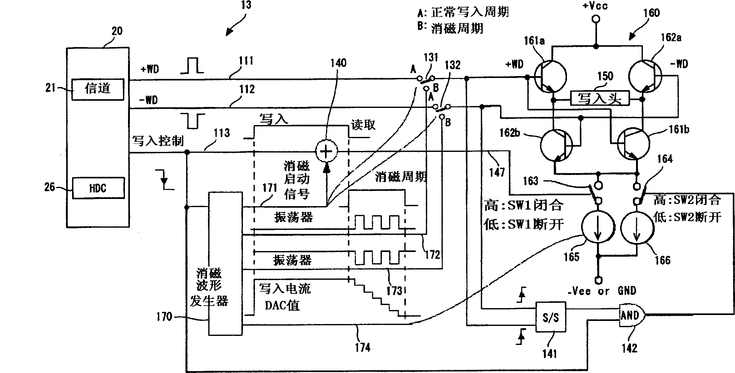
[0102] The following will refer to Figure 5 An HDD according to the second embodiment is described. Figure 5 A part of the construction of AE is described. The basic structure of the HDD according to the present embodiment will not be described because it is the same as that part of the HDD according to the first embodiment. Further, the control process performed during the normal writing period is also not described because it is also the same as the case of the first embodiment. In the first embodiment, the current flowing from the current source 166 to the write head 150 is controlled according to the on / off operation of the switch 164 . However, in this embodiment, the current I2 provided by the current source 166 is controlled according to the register value stored in the register 143 of the AE13.

[0103] In this embodiment, the output of the single-shot circuit (S / S) 141 directly enters the image 3 Switch 164 is shown. This ensures that switch 164 is closed duri...


PUM


Abstract

Embodiments of the invention provide a hard disk drive that is capable of performing degaussing promptly and properly and a recording method for use with such a hard disk drive. A hard disk drive according to one embodiment of the present invention comprises a current source for supplying a first current, which flows to a write head for writing data onto a magnetic disk; a current source for supplying a second current, which flows to the write head when the polarity of the first current changes; transistors for reversing the polarity of a current flowing to the write head; and a control circuit for exercising control so that the second current I 2, which flows from the current source to the write head when the polarity of the first current I 1 is reversed, becomes approximately zero before the first current I 1 converges to approximately zero during a degauss period.

Description

technical field [0001] The present invention relates to hard disk drives and recording methods, and more particularly to hard disk drives that degauss write heads and recording methods for use with such hard disk drives. Background technique [0002] Information reading / writing devices using various media such as optical discs and magnetic tapes are widely known in the art. Wherein, a hard disk drive (referred to as HDD hereinafter) as a storage device of a computer is now very popular, so that it becomes one of the indispensable storage devices of today's computer. Moreover, its application is not limited to computer systems, because of its superior characteristics, HDDs are more and more widely used. For example, HDDs are used in moving image read / write devices, car navigation systems, mobile memories for digital cameras. [0003] Each disk used in an HDD has multiple concentric tracks, and each track is divided into multiple sectors. Each sector stores servo data and u...

Claims


Application Information

Patent Timeline
Patent Type & Authority Applications(China)
IPC IPC(8): G11B5/465G11B5/012
CPCG11B5/465G11B5/1278E01D19/086E01D19/125
Inventor 铃木宏昌冈田谦二
Owner HITACHI GLOBAL STORAGE TECH NETHERLANDS BV
Learn More