Fuse cavity structure and electric connection box

A technology of cavity structure and fuse, applied in the direction of electrical components, circuits, emergency protection devices, etc.

Inactive Publication Date: 2010-03-10
YAZAKI CORP
View PDF18 Cites 3 Cited by
  • Summary
  • Abstract
  • Description
  • Claims
  • Application Information

AI Technical Summary

Problems solved by technology

[0025] However, Figure 8 The conventional fuse housing shown is not configured for stably securing a low height fuse, not shown, in fuse housing 220, so it would be desirable to ameliorate this problem

Method used


Image

  • Fuse cavity structure and electric connection box
  • Fuse cavity structure and electric connection box
  • Fuse cavity structure and electric connection box

Examples


no. 1 example

[0054] Hereinafter, a first embodiment of the fuse cavity structure and the electrical connection box according to the present invention will be described in detail by referring to the accompanying drawings.

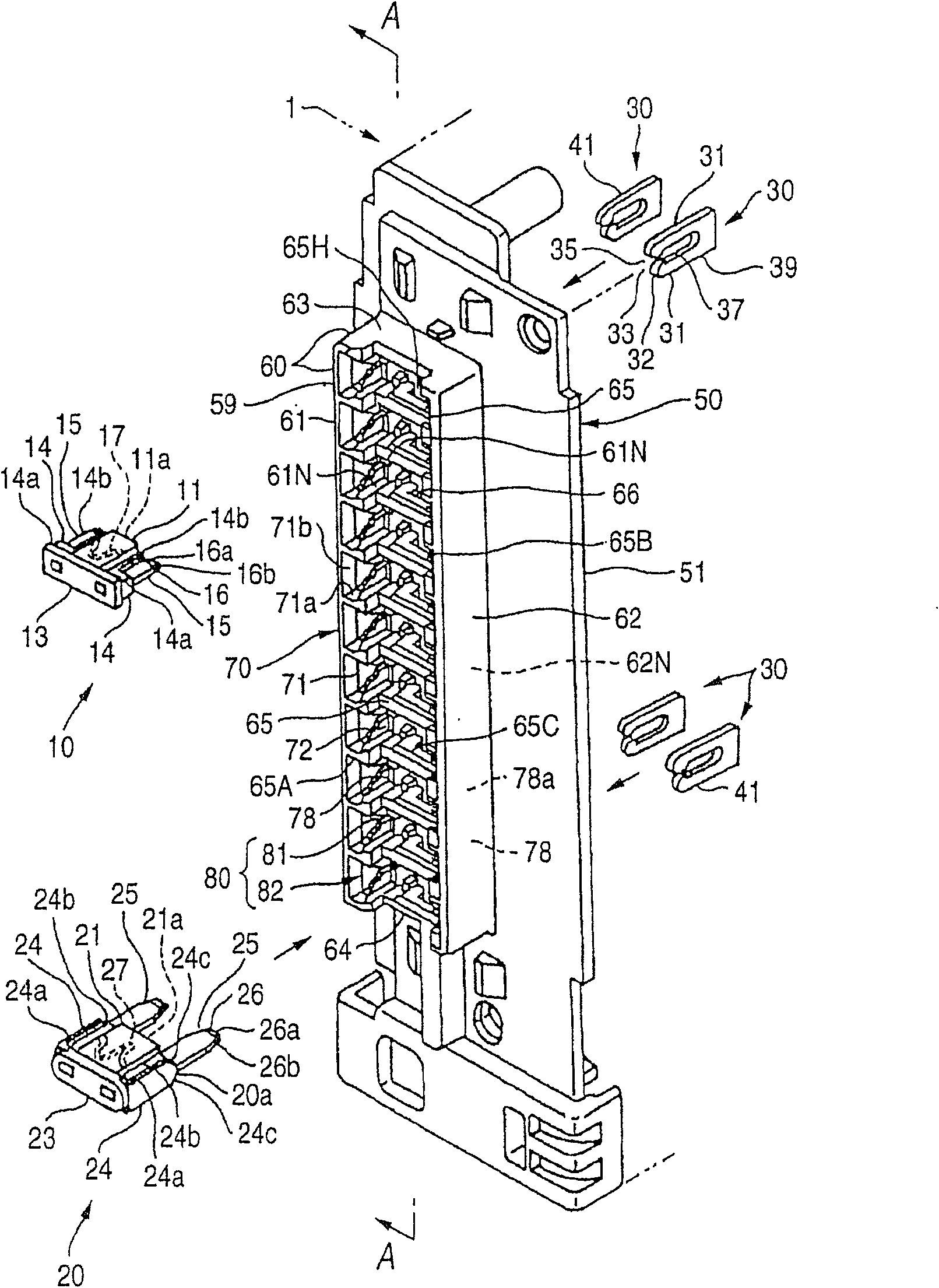
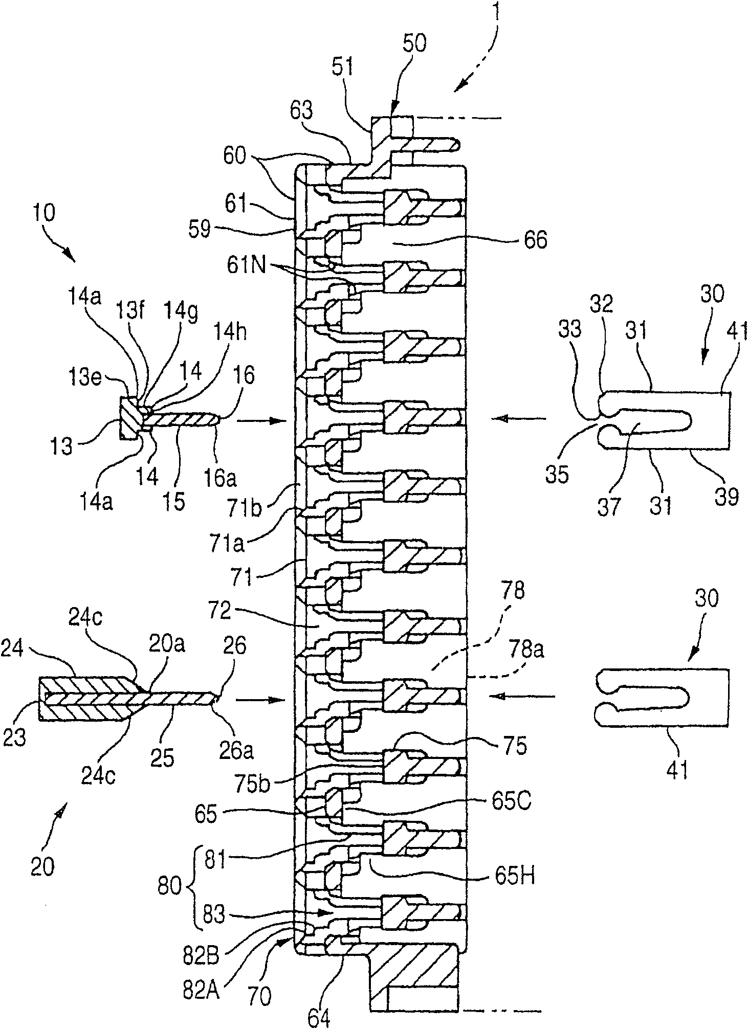
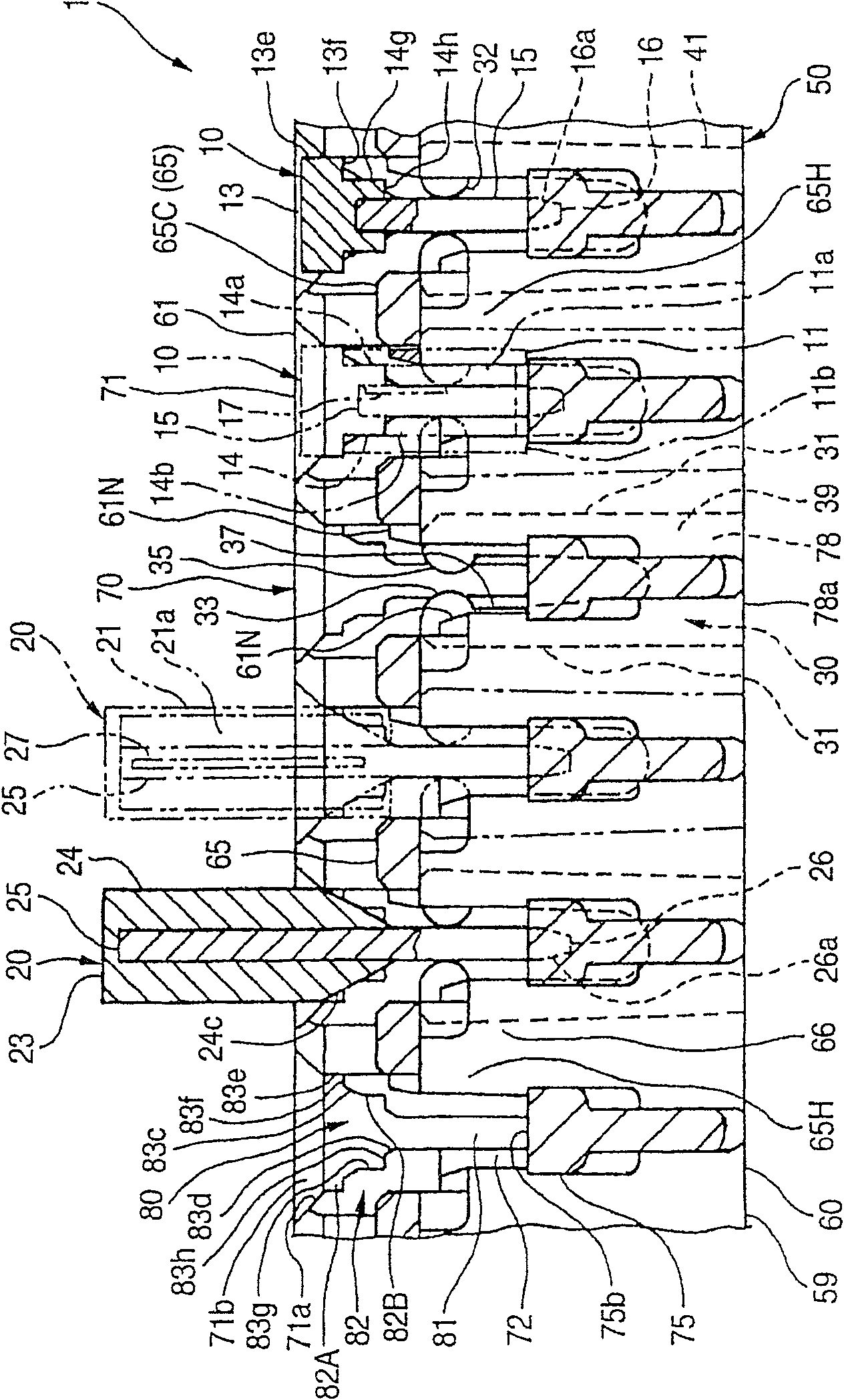
[0055] figure 1 is an exploded perspective view showing a first embodiment of a fuse cavity structure and an electrical connection box according to the present invention, figure 2 is a longitudinal sectional view showing the structure of the fuse chamber and the electrical connection box, while image 3 is an explanatory view showing the structure of the fuse chamber and the electrical connection box.

[0056] Each part of the main part in each figure is shown as a schematic diagram, which is partly simplified, thereby making the main part easy to understand and easy to observe. Also, for the first fuse 10 and the second fuse 20 , overlapping parts are put together for explanation for the sake of convenience.

[0057] Two types of fuses, namely, the first fuse 10 an...

no. 2 example

[0094] A second embodiment of a fuse chamber structure and an electrical connection box according to the present invention will be explained in detail by referring to the accompanying drawings.

[0095] Figure 5 is an exploded perspective view showing a second embodiment of a fuse cavity structure and an electrical connection box according to the present invention, Figure 6 is a longitudinal sectional view showing the structure of the fuse cavity and the electrical connection box according to this embodiment, and Figure 7 is an explanatory view showing the structure of the fuse cavity and the electrical connection box according to this embodiment.

[0096] In order to make the main part of each figure easy to understand, each constituent part is partially shortened, thereby being shown as an easy-to-view schematic diagram. For convenience, the same parts of the first fuse 10 and the second fuse 20 as those of the first embodiment of the present invention are explained toge...


PUM


Abstract

Fuse cavity structure includes fuses 10, 20 in which each of fusible elements 17, 27 for protecting a circuit from overcurrent is located between terminals 15 or 25, and a housing 59 in which the fuses 10, 20 are mounted; a part of a wall 65 of the housing 59 which partitions the fuse 10, 20 and fuse 10, 20 is removed thereby to form a notch 65 H in the wall 65; and space is proved between the fuses 10 or 20. The notch 65 H is formed by notching the wall 65 corresponding to at least a part of the fusible portion 17, 27.

Description

technical field [0001] The present invention relates to a fuse chamber structure in which various types of fuses can be attached, size reduction is performed, and improvement regarding heat generation is performed; and an electrical connection box equipped with the fuse chamber structure. [0002] The present invention further relates to a fuse chamber structure which can perform size reduction and in which various kinds of fuses can be attached and stably fixed, and also relates to an electrical connection box having the fuse chamber structure . Background technique [0003] Figure 7 One example about the structure of a conventional fuse attaching portion is shown, as shown in Unexamined Japanese Patent Laid-Open No. 2002-124175. [0004] The tab terminal pair 155 protrudes from the insulating case 153 in the direction in which they are attached into the fuse attaching portion 120 , which constitutes the first fuse 150 . The tab terminal pair 155 constituting the first f...

Claims


Application Information

Patent Timeline
Patent Type & Authority Patents(China)
IPC IPC(8): H02G3/08H01H85/50
Inventor 久保田胜弘
Owner YAZAKI CORP
Why Eureka
Try Eureka