Timepiece

A technology of clocks and display components, applied in the field of clocks and watches, can solve the problems of not being able to know the best date for maintenance accurately, and it is difficult to know the driving time of the clock, etc., and achieve the effect of maintaining performance for a long time

Inactive Publication Date: 2007-08-29
SEIKO EPSON CORP
View PDF1 Cites 7 Cited by
  • Summary
  • Abstract
  • Description
  • Claims
  • Application Information

AI Technical Summary

Problems solved by technology

[0006] However, in the existing timepieces, there is a problem that the best date for maintenance cannot be accurately known
As a solution to this problem, it is conceivable to record the date of manufacture and sale in advance, for example, to carry out maintenance after five years. However, it is also considered that the clock is stored without being driven for a long time. It is difficult to know the driving time of the clock

Method used


Image

  • Timepiece
  • Timepiece
  • Timepiece

Examples


Embodiment approach 1

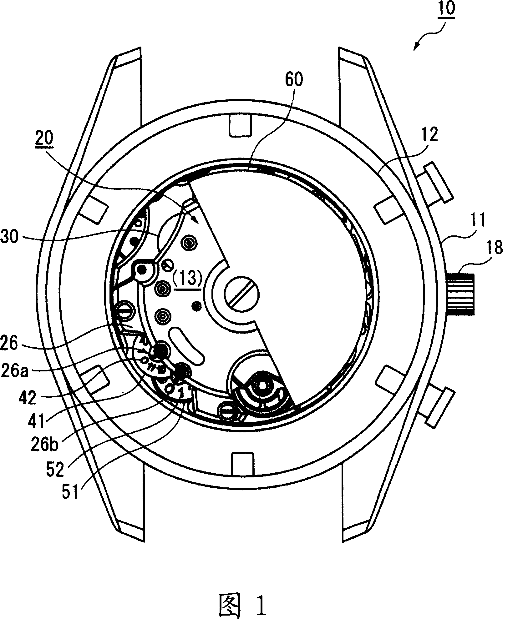
[0054] FIG. 1 is a plan view showing the appearance of a timepiece 10 according to Embodiment 1 viewed from the back cover side. In FIG. 1 , the timepiece 10 of the present embodiment is constituted by a case and a movement 20 accommodated inside the case. not shown) constitutes.

[0055] In this embodiment, a mechanical chronograph wristwatch is exemplified, and has, as an external operation part: a crown 18 at the three o'clock direction of the clock; The operating twist. A crystal 13 as a transparent member is formed at the center of the back cover 12, through which most of the movement 20 can be observed.

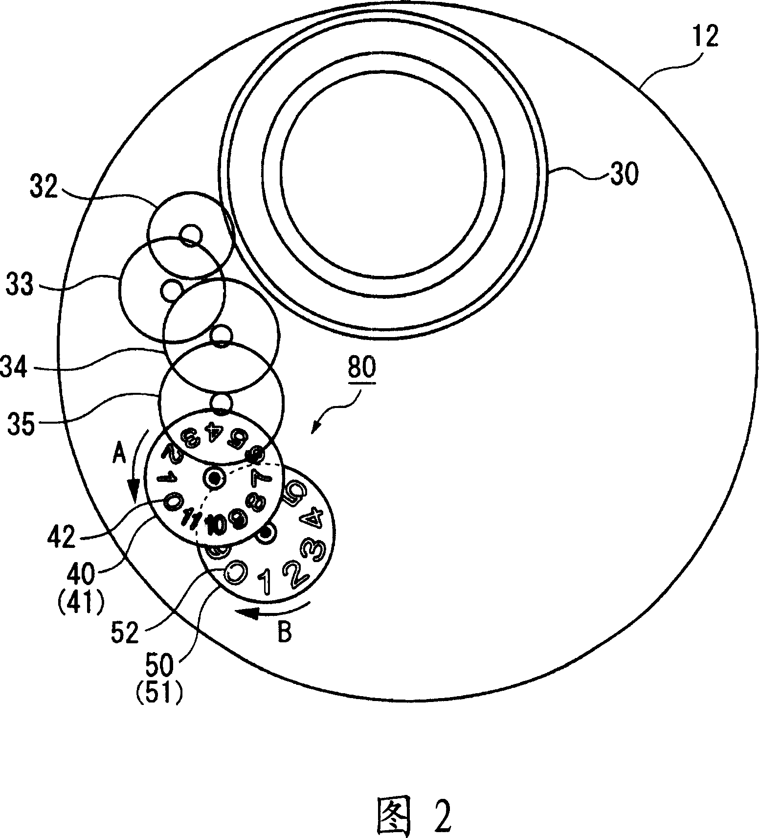
[0056]In the eight o'clock direction when viewed from above, the month unit display gear 41 and the year unit display gear 51 are provided below the rotating pendulum bridge 26 as the display panel of the cumulative driving time display member, and the month unit display gear 41 and the year unit display The gear 51 is arranged so that the month unit display gear 41 ...

Embodiment approach 2

[0087]Next, a timepiece 10 according to Embodiment 2 of the present invention will be described with reference to the drawings. Compared with the above-mentioned Embodiment 1 which uses the month-unit display gear 41 and the year-unit display gear 51 as the display members for displaying the accumulated driving time, Embodiment 2 has the feature of using hands to display the accumulated driving time. Therefore, the description of common parts with Embodiment 1 will be omitted, and the common parts will be described with the same reference numerals.

[0088] FIG. 7 is a partial cross-sectional view showing the cumulative driving time display mechanism 80 according to the second embodiment. In FIG. 7 , the top shaft of the pinion 43 of the fourth intermediate accumulator wheel 40 extends through the fourth clamping plate 25 , and the month display pointer 44 is axially fixed on the top shaft. In addition, the top axis of the accumulation wheel shaft 53 of the accumulation wheel...

Embodiment approach 3

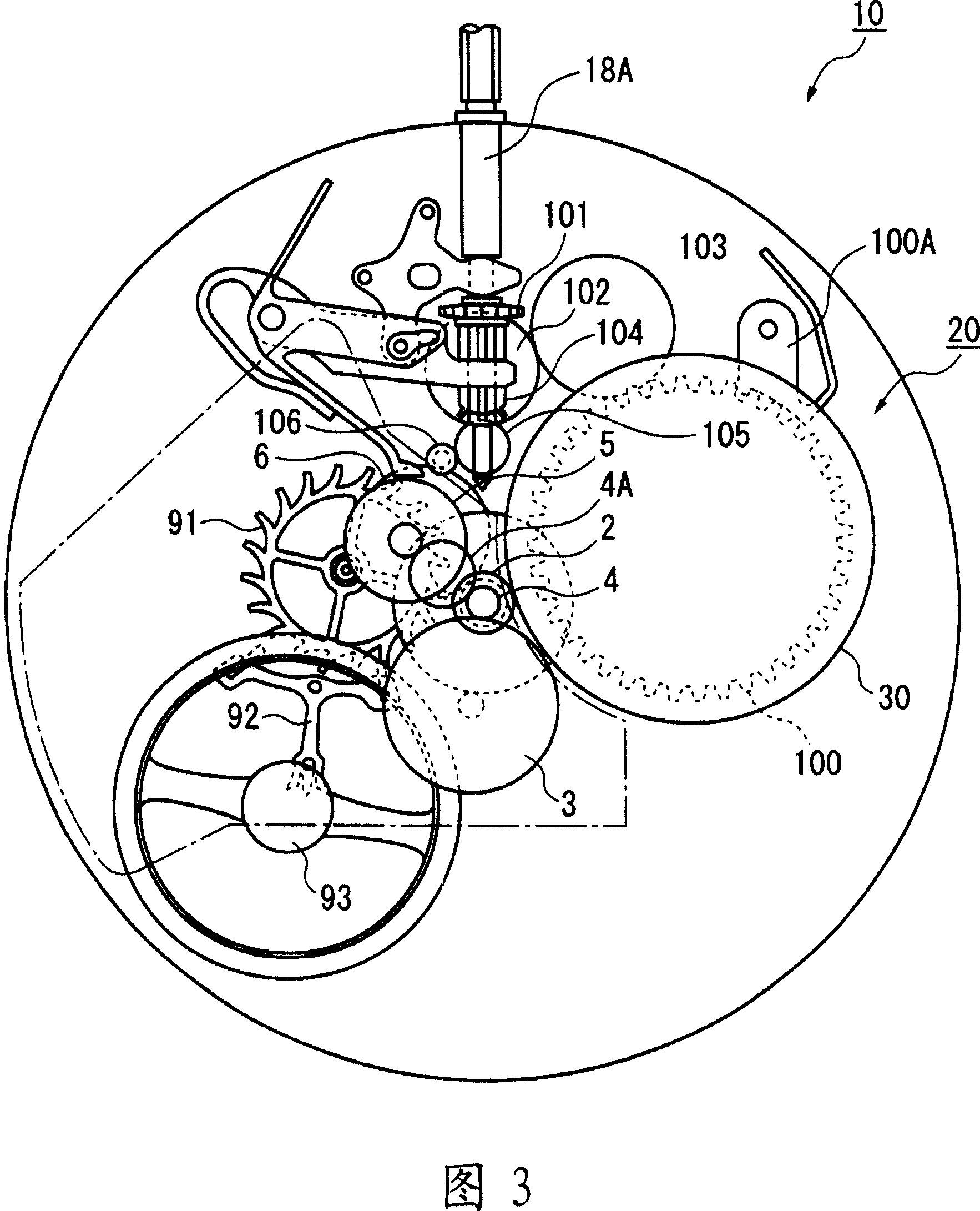
[0096] In the timepiece 10 of Embodiment 3 shown in FIGS. 9 and 10 , a power storage train 110 that adjusts the amount of winding and unwinding of the mainspring is provided.

[0097] The power storage wheel train 110 includes: a power storage pin wheel 112 to which is fixed a power storage pin 111 for displaying the remaining amount of duration; an irregularly shaped intermediate wheel 113 which meshes with the power storage pin wheel 112; a first sun gear 114 , which meshes with the intermediate gear 113; the planetary gear 115, which has a first planetary gear 115A meshing with the sun gear 114A of the first sun gear 114 and a second planetary gear 115B integrated with the first planetary gear 115A; the sun gear 116, which meshes with the second planetary gear 115B of the planetary gear 115; and the planetary intermediate gear 117, on which the planetary gear 115 is mounted.

[0098] The second sun gear 116 is connected to the large steel wheel 100 through the second transf...


PUM


Abstract

A timepiece enables knowing the cumulative drive time indicating how long the timepiece was actually operating. The timepiece 10 has a movement 20, hands disposed to the time display wheel train of the movement 20 for indicating the time, and a month display ring 41 and year display ring 51 that are connected to the movement 20 and count how long the drive source has been driving inside a case. The movement 20 includes a movement barrel 30 housing a spring as the power source, a time display wheel train linked to rotation of the movement barrel 30, and a cumulative drive time display mechanism that operates in conjunction with rotation of and transfers torque from the movement barrel 30. The case includes at least a crystal, a casing 11, and a back cover 12. Part of the back cover 12 is transparent to enable viewing the month display ring 41 and year display ring 51.

Description

technical field [0001] The present invention relates to a timepiece. In detail, the present invention relates to a structure of a timepiece having a cumulative driving time display mechanism which displays the cumulative driving time during which the timepiece is driven. Background technique [0002] In the prior art, some timepieces have the function of displaying the current time, elapsed time, calendar, and many other information related to time and time by means of hands, display panels, and the like. [0003] For example, there is a timepiece called a chronograph that measures elapsed time, and a timepiece that displays elapsed time with a chrono second hand, chrono minute hand, chrono hour hand, etc. is known (for example, refer to Patent Document 1). [0004] Patent Document 1: Japanese Patent Application Laid-Open No. 9-178868 [0005] In such Patent Document 1, the integrated measurement of the time desired to be measured is performed by manipulating the external ...

Claims


Application Information

Patent Timeline
Patent Type & Authority Applications(China)
IPC IPC(8): G04B1/10G04B19/04
CPCG04B9/005G04C10/04G04F8/00G07C3/045
Inventor 神谷秀树平谷荣一
Owner SEIKO EPSON CORP
Why Eureka
Try Eureka