Supercharge Your Innovation With Domain-Expert AI Agents!

Reciprocating electric shaver

一种电动剃须刀、往复式的技术,应用在金属加工等方向,能够解决结构复杂等问题,达到清扫容易、清扫作业性改善、构造简单的效果

Inactive Publication Date: 2008-02-13
IZUMI PROD CO
View PDF1 Cites 5 Cited by
  • Summary
  • Abstract
  • Description
  • Claims
  • Application Information

AI Technical Summary

Problems solved by technology

However, in this case, a connection mechanism between the outer blade frame and the main body is required, that is, a mechanism for transmitting the movement of the operating member on the main body side to the floating pressure adjustment mechanism on the outer blade frame side, so the structure becomes complicated.

Method used


Image

  • Reciprocating electric shaver
  • Reciprocating electric shaver
  • Reciprocating electric shaver

Examples


Embodiment 1

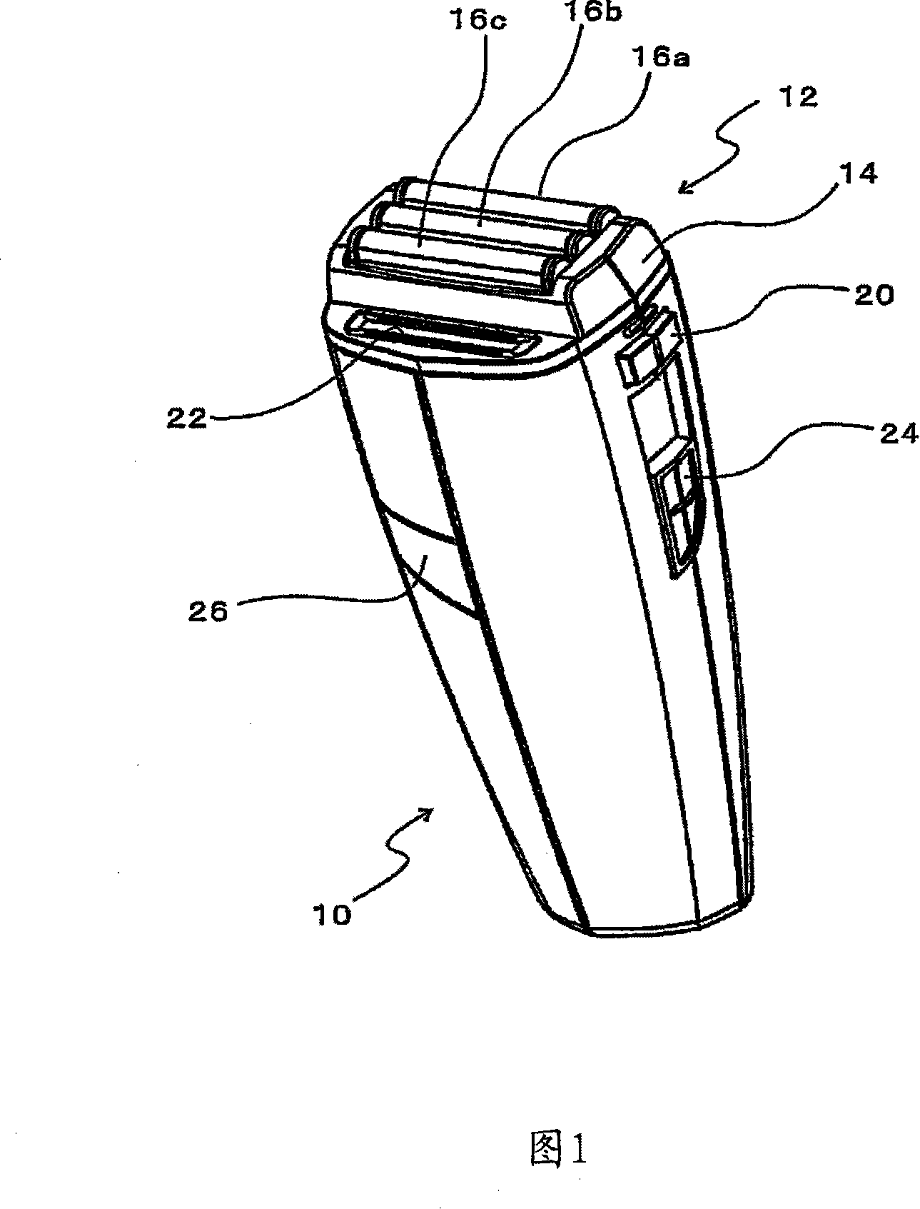
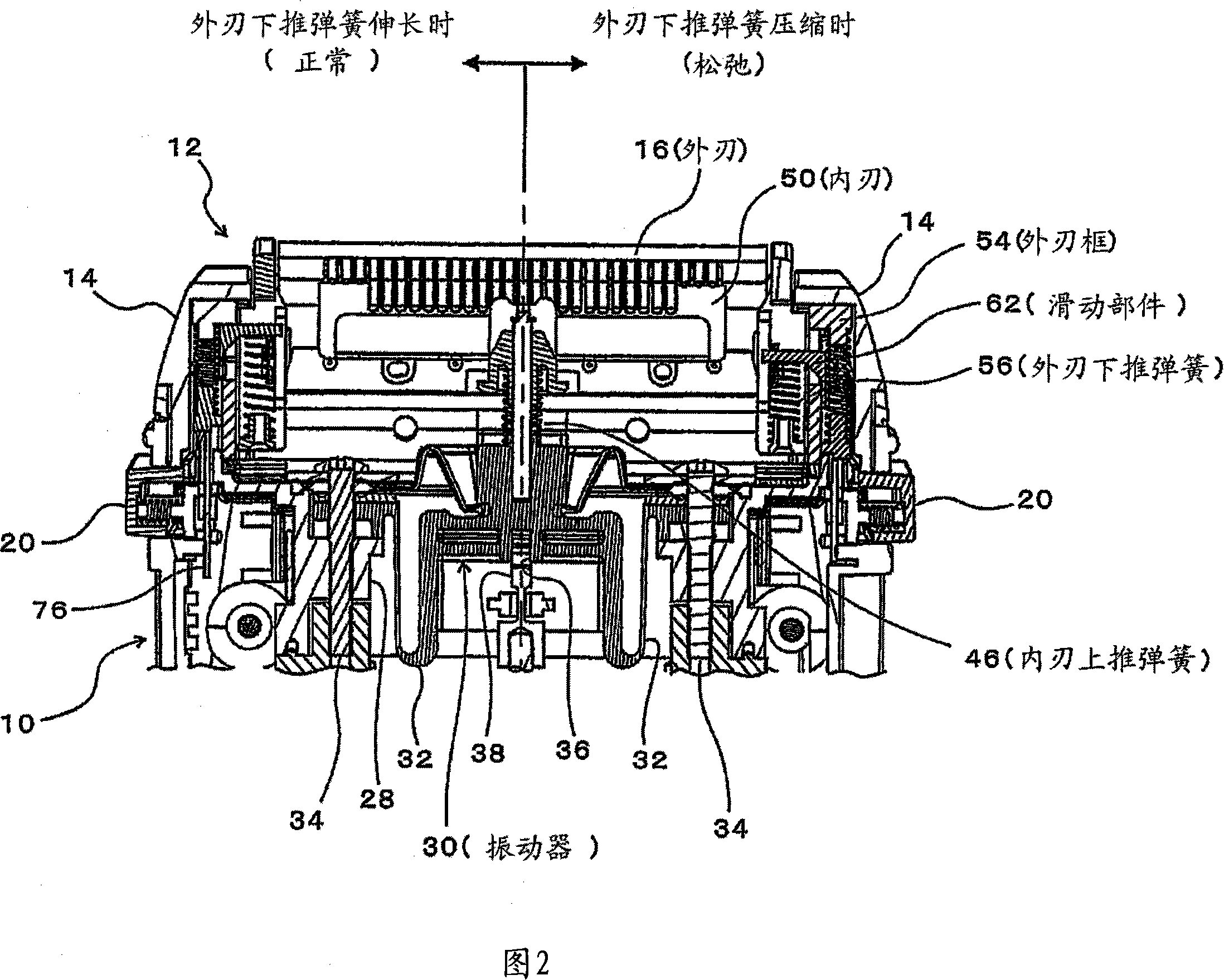
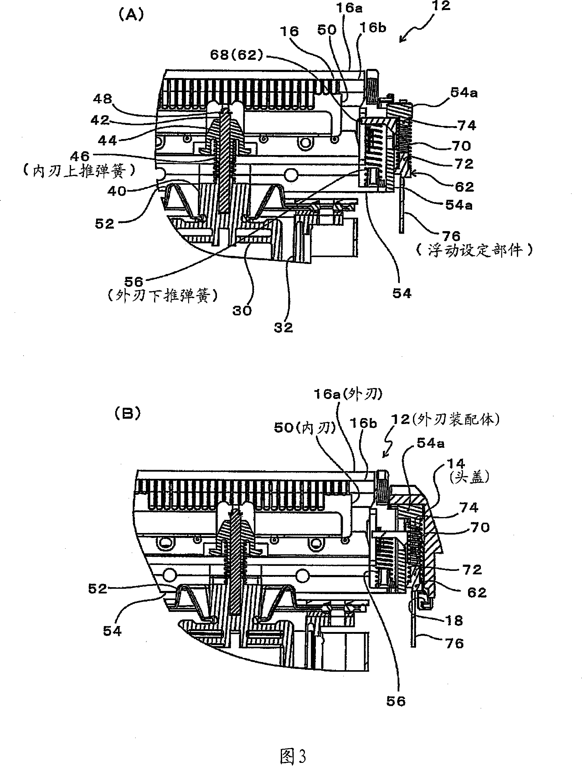
[0040] 1 is a perspective view showing the appearance of an embodiment of the present invention, and FIG. 2 is a longitudinal sectional view of the head in FIG. 1 , and is a sectional view along the central outer blade. In addition, from the center in FIG. 2 , the left half shows a state where the floating pressure of the outer blade is strong or normal (normal), and the right half shows a state where the floating pressure of the outer blade is weakened (relaxed). Fig. 3 is a partial enlarged view of Fig. 2, (A) shows the state (corresponding to the left half of Fig. 2) with strong floating pressure on the outer blade (corresponding to the left half of Fig. 2), and (B) shows the state with weak floating pressure on the outer blade (relaxed , which is equivalent to the right half of Fig. 2). Fig. 4 is an exploded perspective view of the head, and Fig. 5, Fig. 6 and Fig. 7 are, respectively, a sectional view, a bottom view and a rear view showing the mechanism for adjusting the ...


PUM


Abstract

A reciprocating shaver including an inner cutter upwardly pushing spring for pressing the inner cutter against the inner surface of the outer cutter; slide members held on the outer cutter frame so as to be able to slide; outer cutter elastically supporting members which are for elastically supporting the outer cutter and mounted in the outer cutter frame with one end of each one of them engaging one of the slide members, and another end thereof engaging the outer cutter; and float setting members which are provided in the shaver main body and respectively engage the slide members, in linkage with the mounting motion of the outer cutter frame relative to the shaver main body, so as to determine the position of the slide members.

Description

technical field [0001] The present invention relates to a reciprocating electric shaver, which shaves beards on the face by reciprocating the inner blade while pushing the inner blade to the inner surface of the substantially inverted U-shaped outer blade in side view. Background technique [0002] There is known a reciprocating electric shaver, which pushes the inner blade to the inner surface of the outer blade which is generally inverted U-shaped in side view, while reciprocating the inner blade, passing the inner blade To shave off the beard that gets into the slit provided on the outer edge. [0003] (Patent Document 1) Japanese Patent Application No. 2004-340838 [0004] Patent Document 1 shows a shaver in which the outer blade is slidably held on the outer blade frame in the up and down direction. The applied inner blade is pushed against the inner surface of the outer blade to reciprocate the inner blade. That is, the inner blade is held on a vibrator that is exci...

Claims


Application Information

Patent Timeline
Patent Type & Authority Applications(China)
IPC IPC(8): B26B19/02B26B19/28
CPCB26B19/046
Inventor 柴伸治
Owner IZUMI PROD CO
Features
  • R&D
  • Intellectual Property
  • Life Sciences
  • Materials
  • Tech Scout
  • Unparalleled Data Quality
  • Higher Quality Content
  • 60% Fewer Hallucinations
Learn More