Lighting device for vehicle and method of manufacturing the same

A manufacturing method and technology for lamps, which are applied in the direction of headlights, road vehicles, household appliances, etc., can solve the problems of low cost, reduced specular reflectivity, difficulty in improving the appearance effect and high-end feeling, etc.

Active Publication Date: 2008-03-19
KOITO MFG CO LTD
View PDF3 Cites 4 Cited by
  • Summary
  • Abstract
  • Description
  • Claims
  • Application Information

AI Technical Summary

Problems solved by technology

However, in the technique of processing the fine uneven surface on only a part of the surface of the molding resin, a mask for exposing only a part of the surface is formed by a photographic method, the fine uneven processing is performed on the surface, and after the processing is completed, the surface is removed. The process of masking becomes necessary, etc., and the number of processes increases, making it difficult to achieve low cost
[0009] In addition, the resin in Patent Document 2 is not based on the premise of applying the technology of forming an aluminum vapor-deposited film on the surface to form a glossy or semi-glossy surface as in Patent Document 1. Therefore, if an aluminum vapor-deposited film is actually formed on the surface by direct vapor deposition, it will be difficult. Due to the difference in shrinkage between the resin after molding and vapor deposition and the temperature drop of the aluminum vapor deposition film, unevenness may occur on the surface, and the regular reflectance may decrease and a mirror surface may not be obtained.
Therefore, considering that it is difficult to apply to motor vehicle lights
In addition, as in Patent Document 3, it is proposed to implement embossing on the extended part to diffuse the light from the light source, and further diffuse the light irradiated to the area other than the effective reflection surface to reduce the dazzling light. However, due to the embossing The surface is not a semi-gloss surface, so it is difficult to obtain the effect of improving appearance and sense of luxury as described above
In addition, in order to reduce the light reflectance of the area other than the effective reflection surface, it is also considered to apply a paint with a low reflectance, but there is a problem that a special process for coating is required and the cost is high.

Method used


Image

  • Lighting device for vehicle and method of manufacturing the same
  • Lighting device for vehicle and method of manufacturing the same
  • Lighting device for vehicle and method of manufacturing the same

Examples


no. 1 example

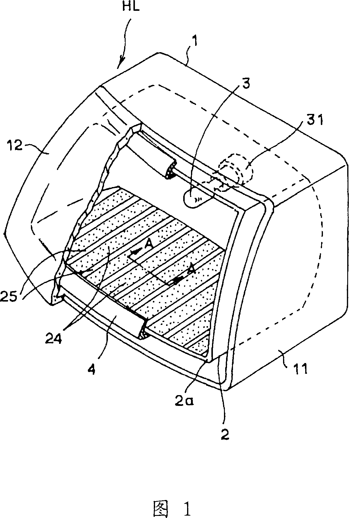
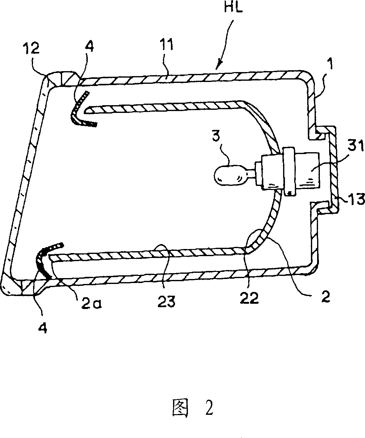
[0023] Next, a first embodiment of the present invention will be described with reference to the drawings. FIG. 1 is a partially cut away perspective view of a first embodiment of a headlamp HL in which the present invention is applied to an automobile, and FIG. 2 is a longitudinal sectional view thereof. In these figures, a lamp body 11 having a substantially rectangular front shape, a front lens 12 made of transparent resin attached to the front opening of the lamp body 11, and a rear cover 13 covering the rear opening of the lamp body 11 are formed. A lamp housing 1 is formed, and a reflector 2 is built in the lamp housing 1 . An opening of a bulb mounting hole 21 is formed on the back surface of the reflector 2, and an incandescent lamp or a discharge bulb 3 as a light source is mounted by a socket 31. As shown in FIG. The reflector 2 can be tilted up and down, left and right by an adjustment mechanism not shown in the figure, thereby, the position of the central optical ...


PUM

PropertyMeasurementUnit
wavelengthaaaaaaaaaa
thicknessaaaaaaaaaa

Abstract

In a lighting device for a vehicle including a reflector in which an aluminum deposited layer is formed on a surface of a resin member, the resin member is molded through a resin obtained by adding, to a crystalline resin, a filler having a size smaller than a wavelength of a visible light, and a smooth surface and a fine concavo-convex surface are mixed into a surface of the reflector (the resinmember) which is molded. The aluminum deposited layer is directly deposited on the surface of the resin, and the smooth surface is formed as a mirror finished surface and the fine concavo-convex surface is formed as a semiglossy surface. As compared with a case in which the reflector is constituted by only the simple mirror finished surface, the semiglossy surface designed to have a proper area is present so that a sense of gloss can be suppressed as a whole and a sense of high quality can be given.

Description

technical field [0001] The invention relates to a vehicle lamp with a reflector or a simulated reflector, in particular to a vehicle lamp with improved appearance of the reflector and a manufacturing method thereof. Background technique [0002] For automotive lamps, there is known a technique of forming reflectors for reflecting light emitted from a light source to obtain desired light distribution characteristics by resin molding, or dummy reflectors for covering and hiding the gap between these reflectors and the lamp body. (called the extended part), and an aluminum vapor-deposited film is formed on its surface to form a mirror. This is done in order to achieve the purpose of appearance, that is, in addition to forming the reflector as a reflective surface, the extension part viewed from the outside through the front cover of the lamp can also have a sense of gloss, thereby having a sense of unity with the reflector. Polyester, polypropylene, and polyphenylene sulfide a...

Claims


Application Information

Patent Timeline
Patent Type & Authority Applications(China)
IPC IPC(8): F21V7/22F21S8/10F21W101/02F21W107/10
CPCF21V7/22F21S48/1394F21S48/25B29D11/00596F21S48/238F21S41/37F21S43/33F21S43/50Y10T428/269F21V7/24
Inventor 池田利正木幡隆宏
Owner KOITO MFG CO LTD
Why Eureka
Try Eureka