Engine cylinder body
A cylinder block and engine technology, applied in the direction of engine components, machines/engines, cylinders, etc., can solve the problems of unreasonable flow of cooling water, poor ventilation of the valve chamber cover, and insufficiently compact engine structure, etc., to achieve compact structure, Reasonable organization and smooth ventilation
Active Publication Date: 2010-11-24
CHERY AUTOMOBILE CO LTD
View PDF1 Cites 0 Cited by
- Summary
- Abstract
- Description
- Claims
- Application Information
AI Technical Summary
Problems solved by technology
In the current engine cylinder block, there are common problems in the inside of the engine crankcase, the cylinder head and the valve chamber cover. The flow direction is not reasonable and so on.
Method used
View moreImage
Smart ImageViewing Examples


Examples
Embodiment Construction
Login to View More PUM
 Abstract
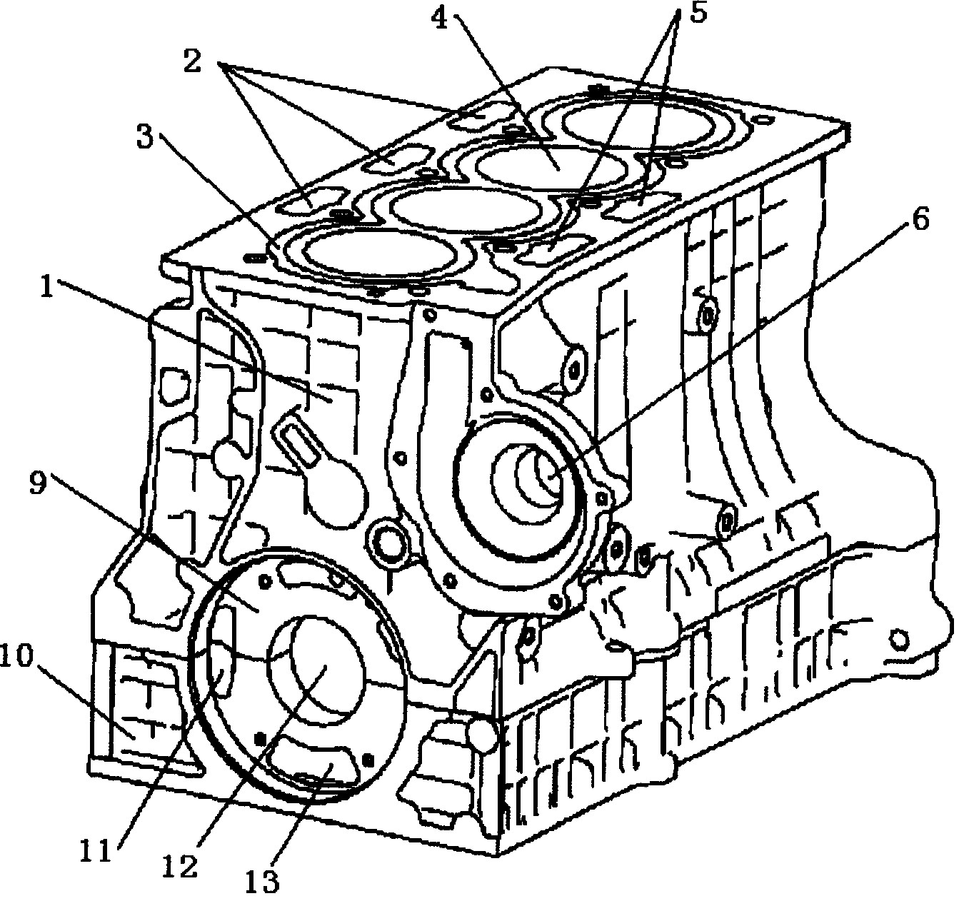
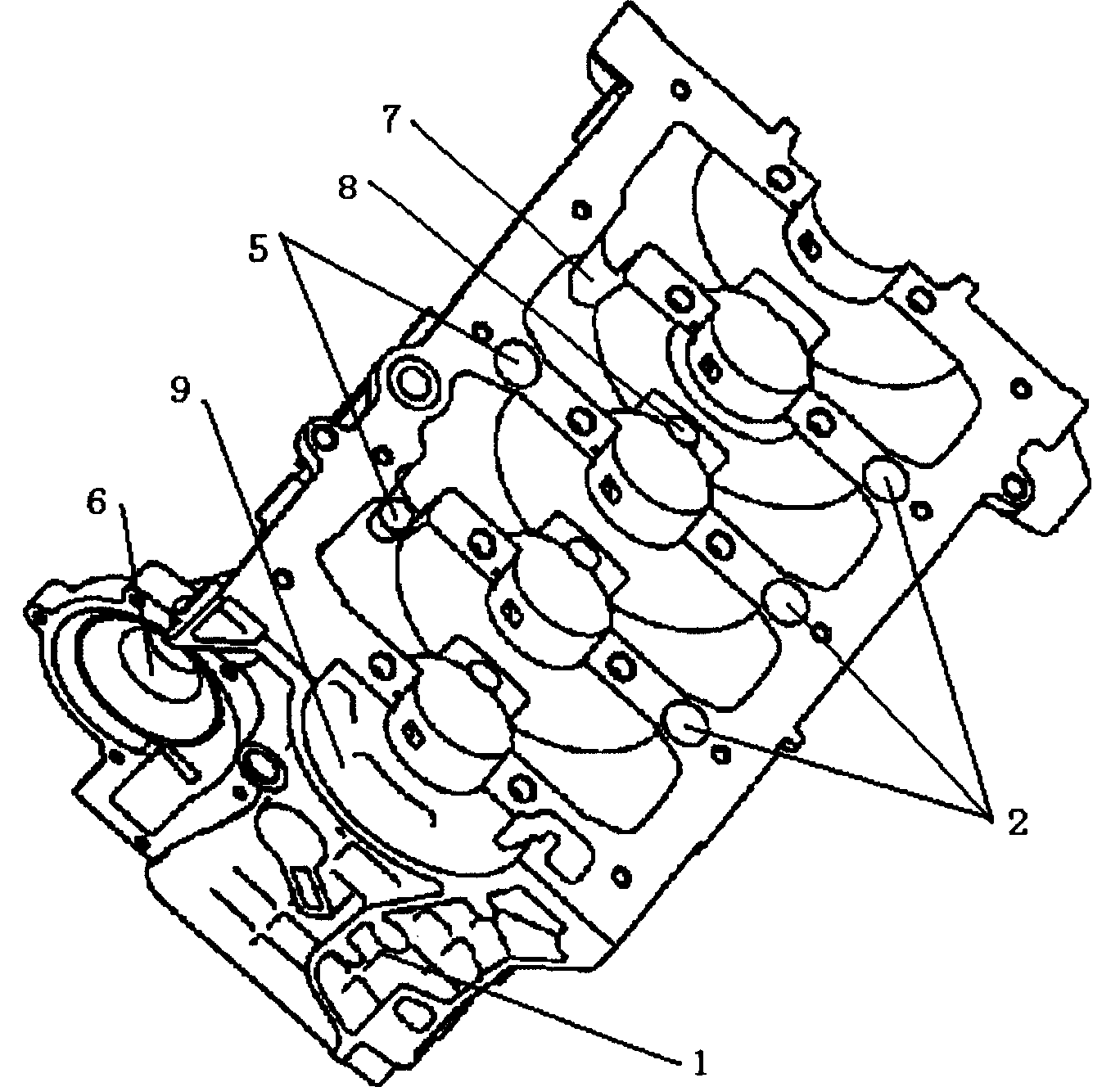
An engine cylinder body comprises a group of cylinders and water jackets which surround the cylinders, the top face of the cylinder body is connected with the cylinder cover, and the bottom of the cylinder body is a crankcase chamber. The cylinder body is characterized in that: ventilation holes passing through up and down are arranged at the air inlet side of the cylinder body. In order to lead the engine oil on the cylinder cover return to a crankcase oil tray, oil return holes passing through up and down are arranged on the cylinder body. In order to balance the pressure in the crankcase chamber, a ventilation hole is arranged in the center of a shaft block of the crankcase. In order to shorten the whole length of the engine, an oil pump mounting snap is arranged at the front end of the cylinder body. The oil return holes and the ventilation holes are designed on the cylinder body, and the oil pump mounting snap is arranged at the front end of the cylinder body, then an oil pump can be directly arranged inside the cylinder body, therefore, the structure is compact and the cooling flow organization is reasonable; slots and holes are arranged on the main bearing base of the cylinder body to lead communication of the adjacent cylinders, therefore the ventilation inside the crankcase is still smooth when the engine is leaned to certain angle.
Description
an engine cylinder block technical field The invention relates to an engine cylinder block. Background technique The cylinder block is the main load-bearing part of the engine. On the one hand, it must bear the impact force generated by the combustion gas explosion. At the same time, the crank and connecting rod mechanism inside the engine is installed on the cylinder block; Above the cylinder block, the structure of the cylinder block determines the structure of the entire engine, which affects the layout of the engine room of the vehicle. In addition, the layout of the cooling water jacket and oil passages on the cylinder block also affects the performance of the cooling system and lubrication system of the entire engine and the overall structure. Due to the limitation of the layout of the whole vehicle, especially the cabin of a car, the engine is required to have a compact structure. Therefore, it is very important to design a cylinder block with a reasonable structur...
Claims
Login to View More Application Information
Patent Timeline
 Patent Type & Authority Patents(China)
IPC IPC(8): F02F7/00F01M1/02F02F1/10F01M13/00
Inventor 朱小平王成罗春刘双寨王桂群
Owner CHERY AUTOMOBILE CO LTD
Features
- R&D
- Intellectual Property
- Life Sciences
- Materials
- Tech Scout
- Unparalleled Data Quality
- Higher Quality Content
- 60% Fewer Hallucinations
Learn More Browse by: Latest US Patents, China's latest patents, Technical Efficacy Thesaurus, Application Domain, Technology Topic, Popular Technical Reports.
© 2025 PatSnap. All rights reserved.Legal|Privacy policy|Modern Slavery Act Transparency Statement|Sitemap|About US| Contact US: help@patsnap.com