Releasing mechanism and leveling apparatus

A release mechanism and processing device technology, which is applied in the field of correction processing devices, can solve problems such as difficult opening movements, large-scale and complicated devices, and achieve the effects of improving the working environment and reducing noise

Inactive Publication Date: 2008-05-07
AIDA ENG LTD
View PDF3 Cites 10 Cited by
  • Summary
  • Abstract
  • Description
  • Claims
  • Application Information

AI Technical Summary

Problems solved by technology

[0007] The above-mentioned devices described in Japanese Patent Laying-Open No. 10-94830 and Japanese Patent Laid-Open No. 5-70719 are released by the cylinder in conjunction with the stamping process carried out in a short cycle, so the switching of the solenoid valve The sound and the collision sound of the cylinder end are loud, so it is necessary to suppress the noise and improve the working environment
[0008] In addition, in the case of the cylinder, there is a long lag time from when the clamping signal for releasing and clamping the workpiece is issued to the leveling and feeding device until the actual working pressure rises to a specified value, so it cannot be used in practice. The release action satisfies the requirement of increasing the number of strokes per unit time (speeding up) during press processing
[0009] As described in Japanese Patent Application Laid-Open No. 5-88706, the device that rotates the eccentric shaft by the motor to perform the release action is preset to an eccentric amount commensurate with the release action, and because the eccentric amount needs to be replaced with an eccentric shaft in order to change the eccentric amount. Due to the different eccentric shafts, it is difficult to perform a large opening movement
Therefore, for example, when the roller is cleaned or the workpiece is passed through the leveling and feeding device, it is necessary to separately provide a mechanism for performing the opening operation separately from the release mechanism that rotates the eccentric shaft by the motor, thereby increasing the size and complexity of the device, and reducing the cost. , setup, assembly, maintainability, etc.

Method used


Image

  • Releasing mechanism and leveling apparatus
  • Releasing mechanism and leveling apparatus
  • Releasing mechanism and leveling apparatus

Examples


no. 1 approach

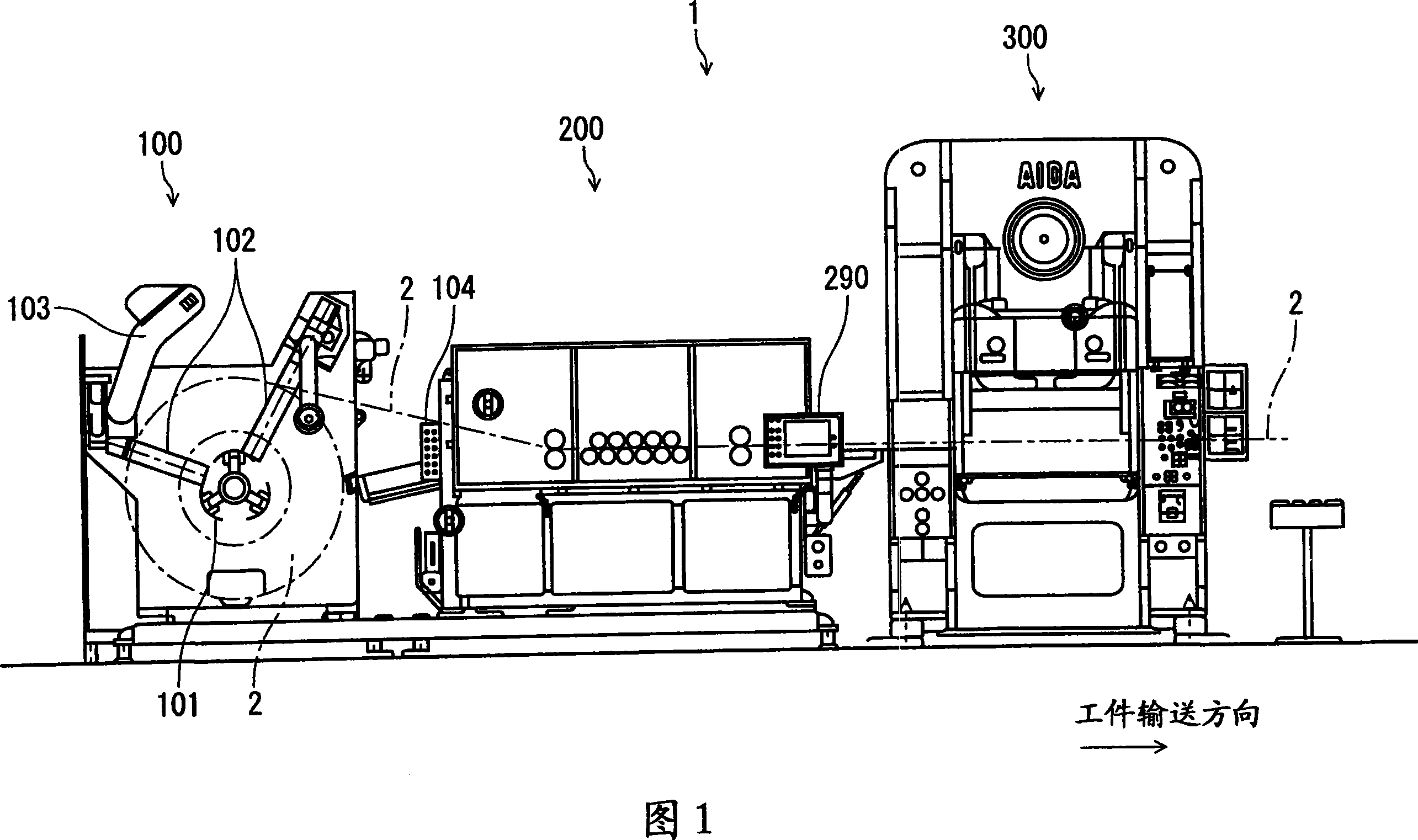
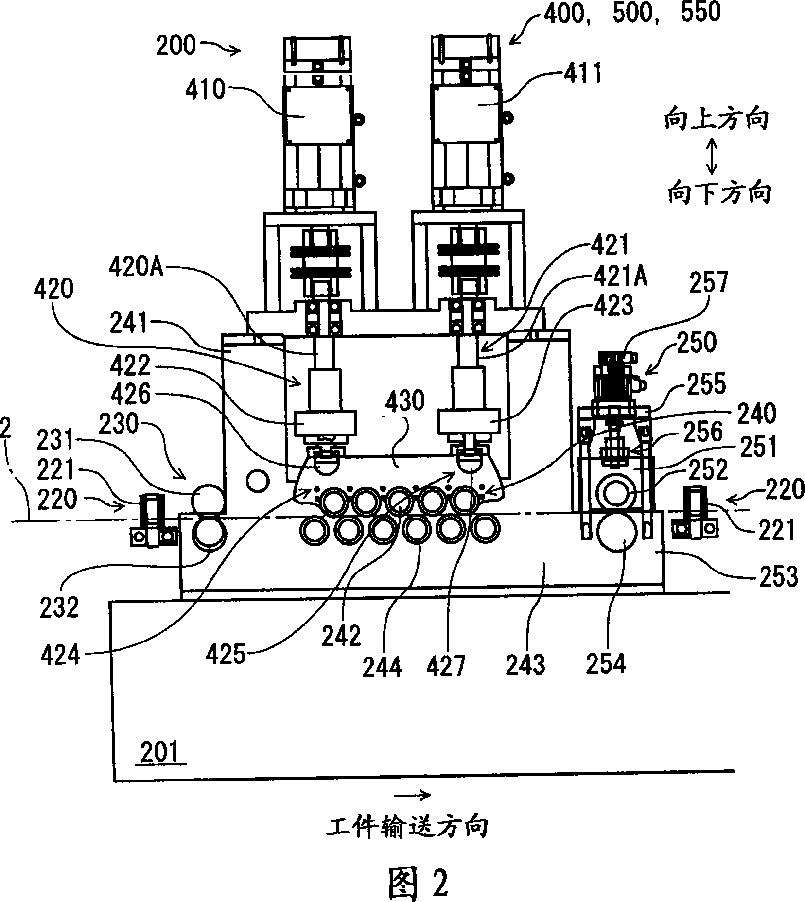
[0054] The automatic punching device 1 in the first embodiment of the present invention, as shown in FIG. The workpiece 2 sent out from the above-mentioned unwinding unit 100 is sent out to the leveling feeding unit 200 of the punching unit 300 downstream of the processing process while correcting deformation such as warping of the workpiece 2, and the above-mentioned leveling feeding unit The stamping section 300 that performs stamping on the workpiece 2 delivered from the section 200.

[0055] The above-mentioned unwinding unit 100 is configured to include: a drum 101, which supports the long workpiece 2 as a coil while being rotated by a motor or the like, and sends the workpiece 2 to the leveling and feeding unit in a predetermined amount one by one. 200; the side guide part 102, which supports the workpiece 2 wound on the drum 101 from both sides so as to prevent the coil from collapsing; and the coil pressing part 103 (holding part), which is used to prevent the And whe...

no. 2 approach

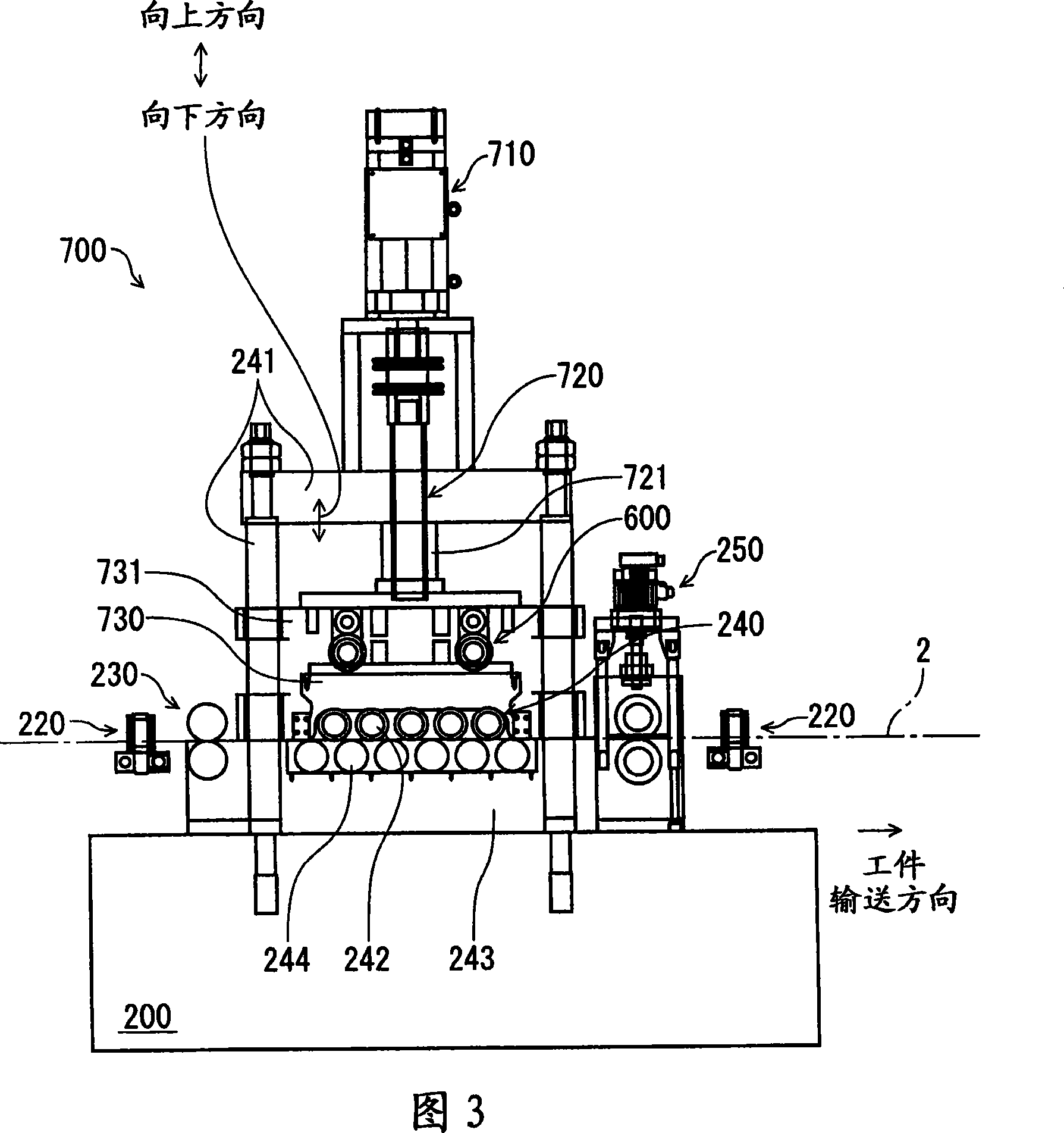
[0110] Next, a second embodiment of the present invention will be described in detail with reference to FIGS. 3 and 4 .

[0111] In addition, since the second embodiment differs from the first embodiment only in the structure of the leveling and feeding unit 700, the leveling and feeding unit 700 will be described, and the same elements will be given the same reference numerals, and detailed description will be omitted. .

[0112] The leveling feed unit 700 of this embodiment is configured to include: a servo motor 710 , a ball screw unit 720 connected to the servo motor 710 , and an upper work roll support member supported by the ball screw unit 720 via a support member 731 . (surface-side work roll support member) 730 .

[0113] The ball screw unit 720 converts the rotational motion of the servo motor 710 mounted on the upper frame 241 substantially integrally with the main body frame 201 into the reciprocating motion of the output member 721 mounted on the on the support ...

no. 3 approach

[0143] Next, a third embodiment of the present invention will be described in detail with reference to the drawings. In addition, the same code|symbol is attached|subjected to the same element as 1st, 2nd embodiment, and detailed description is abbreviate|omitted.

[0144] As shown in FIG. 6 , the automatic punching device 1 of this embodiment is configured to include: an unwinding section 100 that feeds a coiled workpiece 2 to a leveling and feeding section 200 downstream of the processing process; The workpiece 2 sent out from 100, the workpiece 2 is sent out to the leveling feeding part 1200 of the punching part 300 downstream of the processing process while correcting the deformation such as warping of the workpiece 2, and the workpiece sent out from the above-mentioned leveling feeding part 200 2. A press part 300 for performing press work.

[0145] The above-mentioned unwinding unit 100 includes: while supporting the long workpiece 2 wound into a coil shape, the roller ...


PUM


Abstract

A release mechanism for use in a leveling apparatus that performs a leveling process on a work object that has been wound in a coil configuration as a result of the work object being passed between a front side work roll in contact with the front side surface of the work object and a back side work roll that is in contact with the back side surface of the work, wherein the releasing mechanism switches between a work clamp state that allows performance of the leveling process and a release state that releases the work object from the clamp state by displacing a work roll support member that supports one of the work rolls relative to the another support member to change a distance between the work rolls by utilizing rotational movement of an electric motor.

Description

technical field [0001] The present invention relates to a workpiece release mechanism used in a straightening treatment device (leveler) for correcting (correcting) deformation of a workpiece such as winding wrinkles (defects), and a straightening treatment device provided with the release mechanism. Background technique [0002] For example, in the case of pressing a workpiece wound into a coil (e.g., a long plate-shaped metal material), it is necessary to transport it to a press processing device at a predetermined transport speed while correcting its winding wrinkles. As devices for this purpose, various so-called leveling feed devices have been proposed. [0003] In addition, when positioning the workpiece in the stamping processing device, from the perspective of seeking accurate positioning and preventing deformation of the workpiece, it is required that the leveling feed device move the workpiece from the above-mentioned position in the plane or at least in the direct...

Claims


Application Information

Patent Timeline
Patent Type & Authority Applications(China)
IPC IPC(8): B21D1/05
Inventor 吉冈隆
Owner AIDA ENG LTD
Why Eureka
Try Eureka