
Transfer printing fixing device

A fixing device and pad printing technology, which is applied in printing, printing machines, rotary printing machines, etc., can solve the problems of high production cost, damage to the 90-degree rotating cylinder, and crushing of the protruding end of the outer frame, so as to achieve low loss, The effect of reducing production costs

Pending Publication Date: 2017-12-15
中日龙电器制品(杭州)有限公司
View PDF7 Cites 0 Cited by
  • Summary
  • Abstract
  • Description
  • Claims
  • Application Information

AI Technical Summary

Problems solved by technology

This method has the following problems: After the 90-degree rotating cylinder stops moving, the straight-bar press-attached handle will drive the 90-degree rotating cylinder to continue to rotate due to inertia, and this will cause certain damage to the 90-degree rotating cylinder, reducing the 90-degree The service life of the rotary cylinder is high, and the production cost is high; also due to the inertia of the straight bar press-attached handle, when the straight bar press-attached handle turns to the horizontal position, it will not stop immediately, but will continue to move upward for a certain distance, so that it will be easy to move the outer The protruding end of the edge of the frame is smashed (as attached Figure 5 shown), resulting in the scrapping of the outer frame

Method used


Image

  • Transfer printing fixing device
  • Transfer printing fixing device
  • Transfer printing fixing device

Examples


Embodiment Construction

[0028] Below in conjunction with each accompanying drawing, the present invention is described in detail.

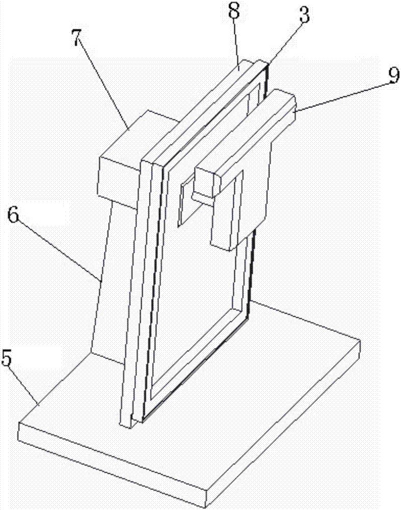
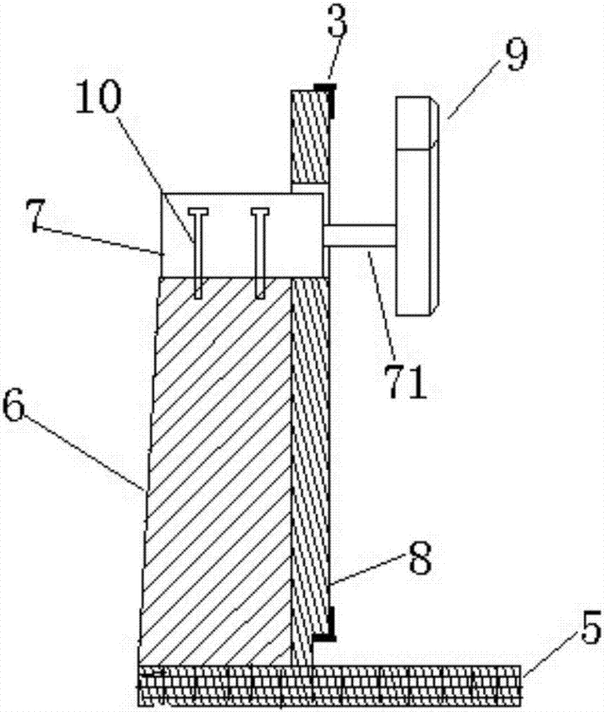
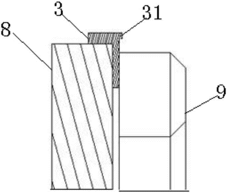
[0029] as attached figure 1 , attached figure 2 and attached image 3 As shown, a pad printing fixing device, a pad printing fixing device, including a substrate 8, a press-attached handle, is characterized in that it also includes a parallel cylinder 7, the substrate 8 is in a vertical state, and a through hole is provided on the substrate 8. The parallel cylinder 7 is installed on the support 6, and the piston rod 71 of the parallel cylinder 7 vertically passes through the through hole of the base plate 8 and connects with the press-attached handle.

[0030] When in use, first put the outer frame 3 on the base plate 8, start the parallel cylinder 7, and the piston cylinder of the parallel cylinder 7 starts to shrink, driving the pressing handle to move closer to the base plate 8, when the pressing handle is attached to the outer frame 3 , the outer frame 3 is fixe...


PUM


Abstract

The application discloses a transfer printing fixing device. The transfer printing fixing device comprises a base plate and a T-shaped pressing attachment handle and is characterized by further comprising a horizontal cylinder, wherein the base plate is in a vertical state, a through hole is formed in the base plate, the horizontal cylinder is mounted on a support base, and a piston rod of the horizontal cylinder perpendicularly penetrates through the through hole of the base plate and is connected with the T-shaped pressing attachment handle. Due to the adoption of the horizontal cylinder, the wear of the device in the use process is small, and the production cost is reduced. Besides, an outer framework cannot be damaged in the fixing process, and the pressing attachment degree of the outer framework can be adjusted according to the pressing attachment demand of the outer framework.

Description

technical field [0001] The invention relates to a fixing device, in particular to a pad printing fixing device. Background technique [0002] Some symbols usually need to be printed on the outer frame of many electronic products. When printing the symbols, the outer frame needs to be fixed to the fixing device first. Traditional fixtures such as attached Figure 4 As shown, it includes a bottom plate, and a 90-degree rotating cylinder is installed on both sides above the bottom plate, and a straight bar press-attached handle is connected to the rotating head of the 90-degree rotating cylinder. When fixing, first put the outer frame on the bottom plate, then 90 degrees The rotary cylinder is started, and the straight bar pressing handle in the vertical state is rotated 90 degrees to a horizontal state, and like this, the straight bar pressing handle has just pressed the outer frame on the base. This method has the following problems: After the 90-degree rotating cylinder sto...

Claims


Application Information

Patent Timeline
Patent Type & Authority Applications(China)
IPC IPC(8): B41F17/00
CPCB41F17/001
Inventor 余建生
Owner 中日龙电器制品(杭州)有限公司
Learn More