Traveling barrel sand-discharging oil-well pump

An oil pump and moving cylinder technology, which is applied in the field of moving cylinder sand discharge oil pump, can solve the problems of easy leakage and insufficient displacement, and achieve the effects of continuously conveying the medium, improving the boosting gear and improving the safety.

Inactive Publication Date: 2008-06-25
金昌昊
View PDF0 Cites 0 Cited by
  • Summary
  • Abstract
  • Description
  • Claims
  • Application Information

AI Technical Summary

Problems solved by technology

[0004] Aiming at the problems existing in the above-mentioned prior art, the present invention designs a moving cylinder sand-discharging oil pump after careful development and multiple tests, which solves the problems of insufficient material supply, displacement and easy leakage in the prior art, and Reduced costs, improved safety and reliability

Method used


Image

  • Traveling barrel sand-discharging oil-well pump

Examples


Embodiment

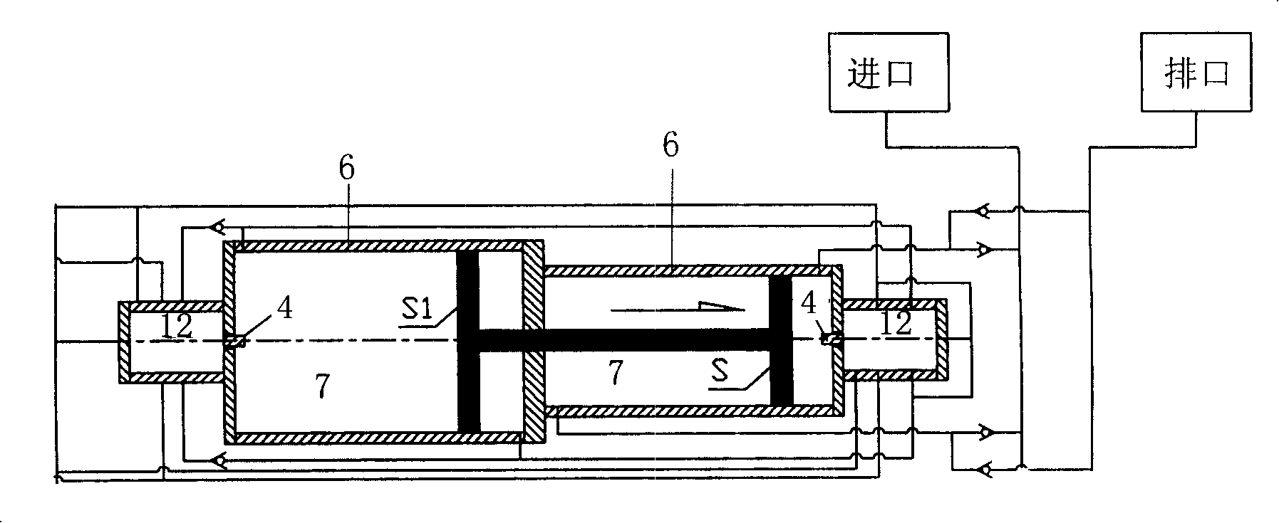
[0013] Below in conjunction with accompanying drawing, specific structure of the present invention is described in detail as follows:

[0014] Such as figure 1 As shown, the two-pole cylinders 6 are connected in series on the same axis line, the pistons of the cylinders 6 are arranged in the cylinder cavity 7, and the two ends of the cylinders 6 connected in series are respectively provided with switching valve groups 12, and the switching valves One end of the contact 4 of the group 12 is set at both ends of the cylinder cavity 7, and a spring 2 is set between the other end of the contact 4 and the inner cavity 15 of the housing 3 of the automatic control switching valve group 12, and the slider 1 runs In the inner cavity 15 , the inner cavity 15 communicates with the pipeline, and the sealing ring 5 is arranged on the contact 4 and the slider 1 .


PUM


Abstract

The invention relates to a traveling barrel sand discharging subsurface pump, wherein, bipolar cylinder bodies are connected on the same axial lead in series, two ends of the cylinder bodies which are connected into a group in series are respectively provided with reversing clapper groups, chambers of shells of the reversing clapper groups are elastically connected with the other ends of contact terminals, slide blocks operate in the chambers, which are communicated with pipelines, sealing elements are arranged on the contact terminals and the slide blocks. The invention reduces the cost, improves the leak tightness, security and reliability.

Description

technical field [0001] The invention relates to an oil well pump, in particular to a moving barrel sand discharge oil well pump. Background technique [0002] At present, there are precedents at home and abroad for using compressed air or liquid as power to increase the mechanical device for conveying fluid medium through a cylinder or liquid cylinder with two poles connected in series. However, under different usage conditions, the medium to be pressurized and conveyed has a different allowable range of pressure difference at the inlet. During the pressurized conveying process, when the pressure at the inlet exceeds the allowable range, insufficient material supply or displacement Insufficient and other abnormal phenomena, resulting in insufficient displacement when selecting booster equipment specifications, or excessively low front-end pressure due to excessive suction, thus affecting the normal operation of the entire pipe network. [0003] In addition, the moving barre...

Claims


Application Information

Patent Timeline
IPC IPC(8): F04B47/08E21B43/00
Inventor 金昌昊
Owner 金昌昊
Why Eureka
Try Eureka