
Clock for world time

A world time and watch technology, applied in the field of world clocks and watches, can solve problems such as inconvenient use and manual calculation of time difference

Inactive Publication Date: 2008-07-02
成厚权
View PDF0 Cites 3 Cited by
  • Summary
  • Abstract
  • Description
  • Claims
  • Application Information

AI Technical Summary

Problems solved by technology

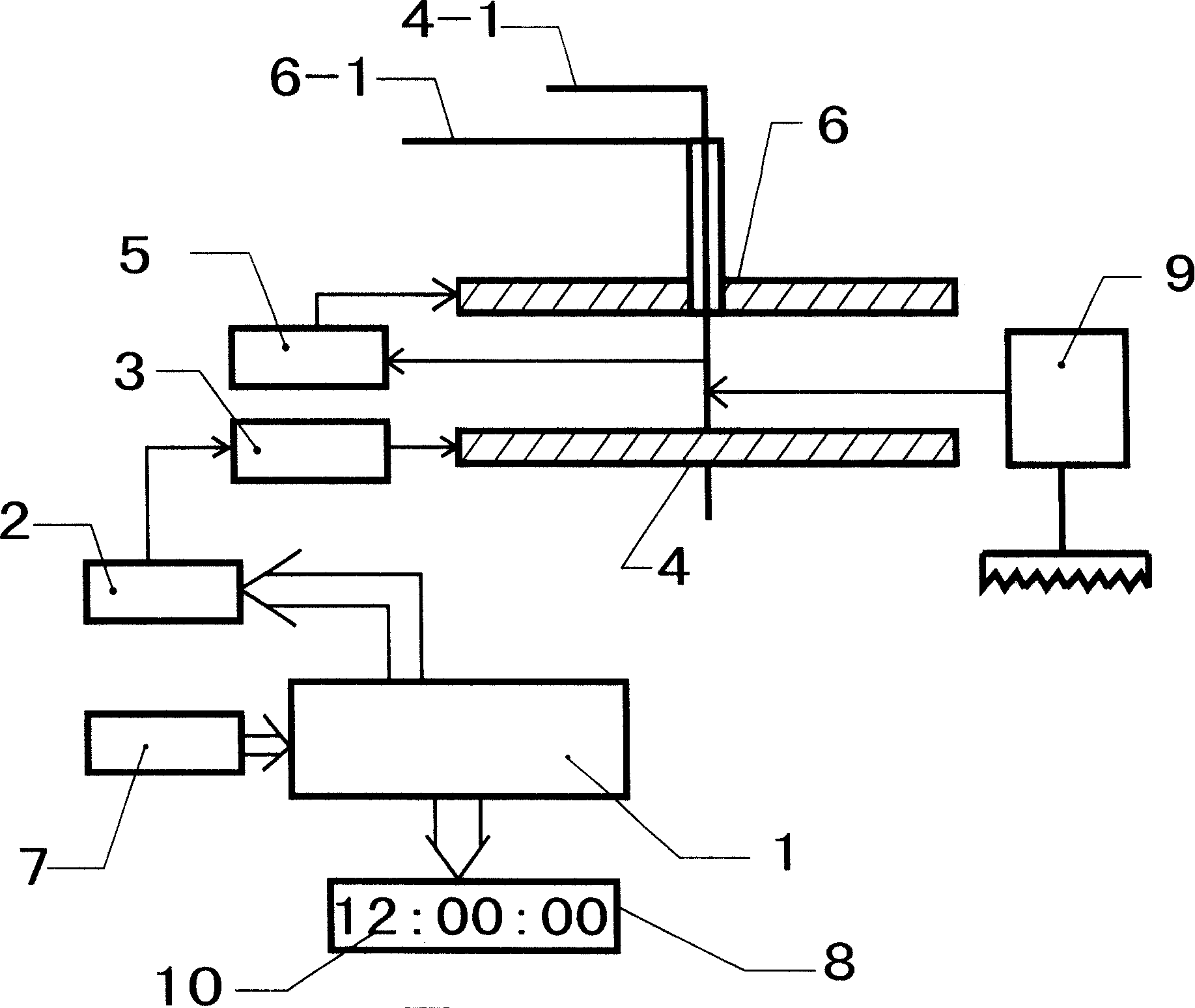
This kind of clock and watch, because will use dialing mechanism 9 to manually adjust the position of hour hand 6-1 minute hand 4-1, and need manually calculate time difference, will bring inconvenience to use like this

Method used


Image

  • Clock for world time
  • Clock for world time
  • Clock for world time

Examples


Embodiment Construction

[0016] The details and working conditions of the specific device proposed according to the present invention will be described in detail below in conjunction with the accompanying drawings.

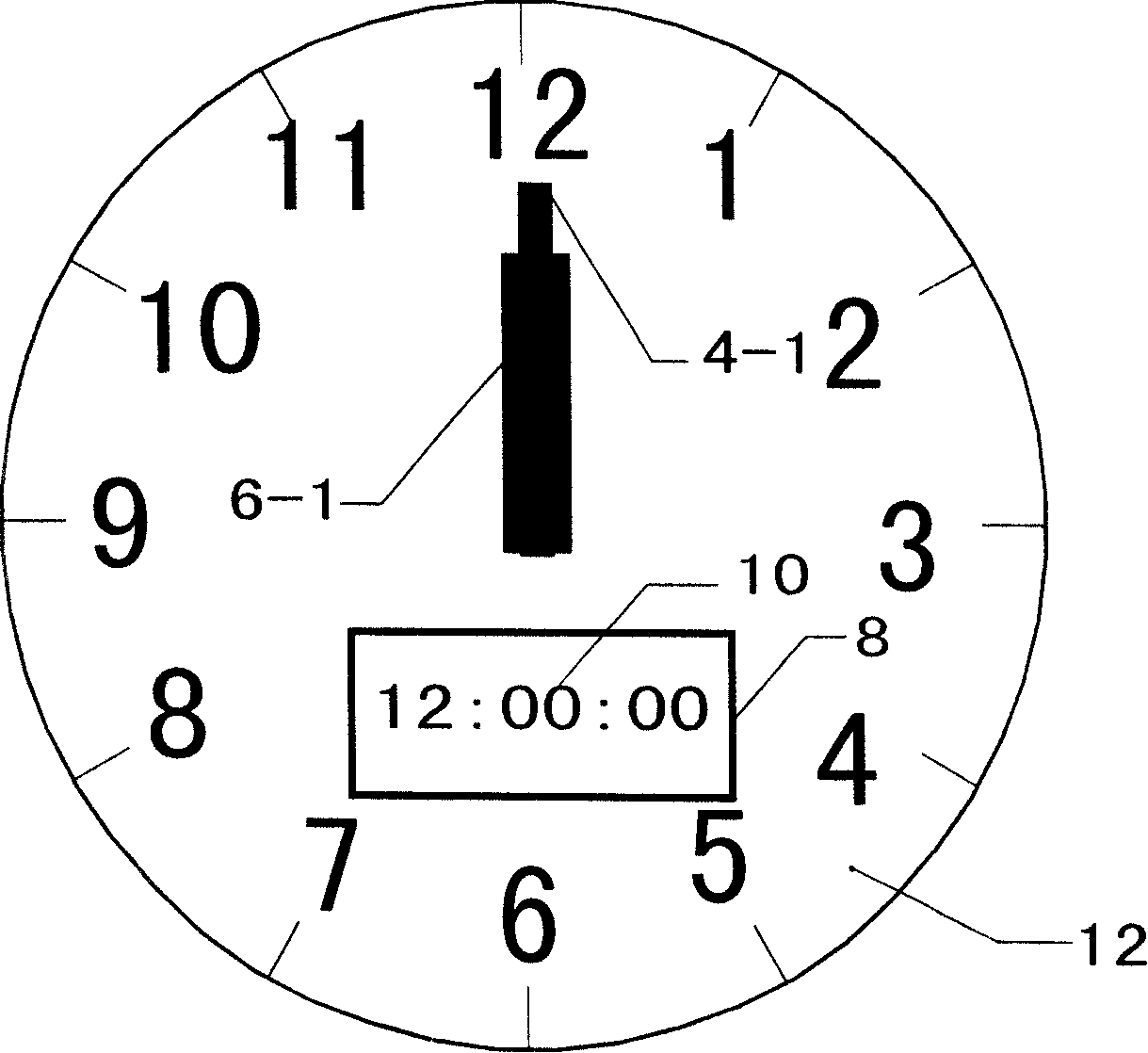
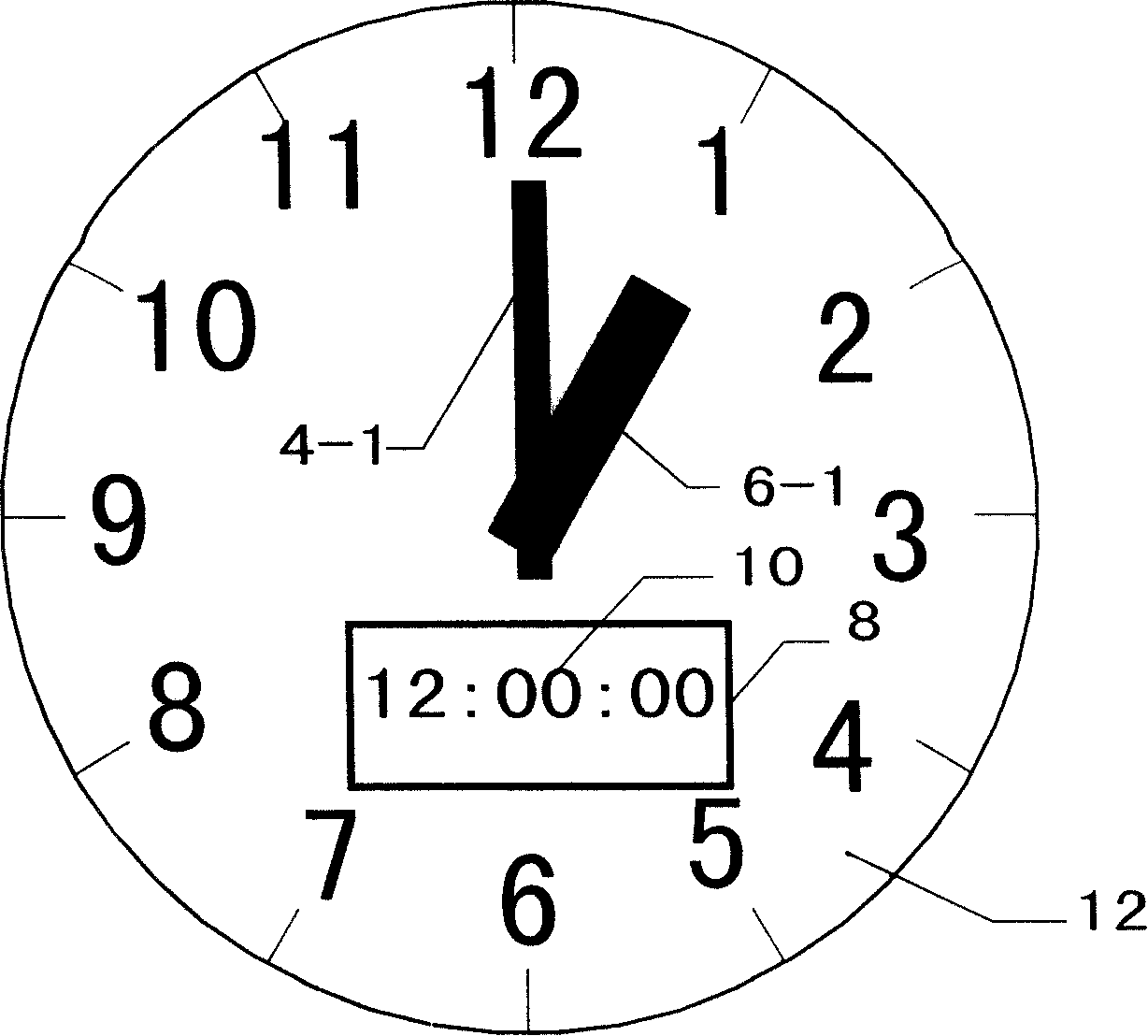
[0017] Depend on Figure 4 , Figure 5 , Figure 6 , Figure 7 , Figure 8 , Figure 9 It can be seen that it includes a microprocessor 1, a motor 2, a transmission gear set 3, a minute wheel 4, a minute hand 4-1, a cross wheel set 5, an hour wheel 6, an hour hand 6-1, a switch set 7, and a digital display 8. Dial 12 (the position of the hour hand 6-1 and minute hand 4-1 in this example refers to the position indicated on the dial 12); the microprocessor 1 is connected to the motor 2, and the motor 2 passes through the transmission gear set 3 is connected with the minute wheel 4, the minute wheel 4 is connected with the hour wheel 6 through the cross wheel group 5, the minute wheel 4 is fixedly connected with the minute hand 4-1, and the hour wheel 6 is fixedly connected with the hou...


PUM


Abstract

The invention provides a world clock, which comprises a microprocessor, a motor, a transmission gear set, a minute wheel, a minute hand, an intermediate wheel set, an hour wheel, an hour hand, a dial, wherein the microprocessor is used for driving the rotation of the motor, the motor is used for driving the rotation of the minute hand and the hour hand via the transmission gear set, the minute wheel, the intermediate wheel set and the hour wheel. The world clock also comprises a photoelectric switch which is connected with the microprocessor, an emitter and an receiver of the photoelectric switch are respectively arranged below the minute wheel and above the hour wheel, and the minute wheel and the hour wheel are provided with a light-transmitting hole and a light screen; a storage unit store with names of cities and time differences between any two cities which is arranged inside the microprocessor; and at least a setting switch and a digital display which are connected with the microprocessor. The device is capable of determining positions of the hour hand and the minute hand on the dial and automatically adjusting the hands to show the time of a selected city, and a digital display thereof is capable of displaying the name of the selected city.

Description

technical field [0001] The invention relates to a world clock, in particular to a world clock with digital and pointer synchronous display. Background technique [0002] Now there is a world clock with digital and analog synchronous display on the market, its structure diagram and working principle are shown in figure 1 , figure 2 and image 3 Shown: it contains microprocessor 1, motor 2, transmission gear set 3, minute hand wheel 4, minute hand 4-1, span wheel set 5, hour hand wheel 6, hour hand 6-1, switch set 7, digital display 8, The dial mechanism 9, the dial 12; the microprocessor 1 is connected with the motor 2, the motor 2 is connected with the minute wheel 4 through the transmission gear group 3, the minute wheel 4 is connected with the hour wheel 6 through the cross wheel group 5, the minute wheel 4 is connected with the minute hand 4-1 is fixedly connected, the hour hand wheel 6 is fixedly connected with the hour hand 6-1; the setting mechanism 9 is connected ...

Claims


Application Information

Patent Timeline
IPC IPC(8): G04C3/00G04G9/00
Inventor 成厚权
Owner 成厚权
Learn More