Machine body of electronic device

A technology for electronic devices and bodies, applied in the direction of electrical equipment casings/cabinets/drawers, electrical components, etc., can solve problems such as the breakage of tenons 130, affecting the assembly quality of the body 100, the appearance of electronic devices, and reducing the structural reliability of the body 100, etc., to achieve The best structural reliability, the improvement of poor assembly quality, and the effect of good assembly quality

Active Publication Date: 2010-06-09
ASUSTEK COMPUTER INC
View PDF5 Cites 0 Cited by
  • Summary
  • Abstract
  • Description
  • Claims
  • Application Information

AI Technical Summary

Problems solved by technology

[0004] Although the original design dimensions of the upper case 110 and the lower case 120 are the same, because the upper case 110 and the lower case 120 will be affected by process tolerances during the manufacturing process, the resulting upper case 110 and the lower case 120 have different lengths or widths, and part of the tenon 130 arranged on the upper case 110 cannot effectively align with the socket 140 arranged on the lower case.
In this way, when the assembler intends to assemble the upper case 110 to the lower case 120, the plurality of latches 130 partially disposed on the upper case 110 cannot be completely aligned with the corresponding sockets 140, resulting in partial latches 130 cannot be inserted into the corresponding socket 140, and the upper shell 110 is not easy to engage with the lower shell 120
[0005] Based on the above, if the assembly personnel forcibly insert some of the latches 130 that cannot be completely aligned into the corresponding sockets 140 (please refer to Figure 1D , which is shown as Figure 1B The side view after the upper shell and the lower shell of the upper shell are engaged with each other), because the length or width of the upper shell 110 and the lower shell 120 are not the same ( Figure 1D The length of the upper case 110 is slightly longer than the length of the lower case 120), and the assembler forcefully inserts some latches 130 that cannot be completely aligned into the corresponding sockets 140, so the upper case 110 and the lower case 120 is prone to deformation ( Figure 1D The upper casing 110 shown has obvious deformation), which causes the surface of the body 100 to bulge, thereby affecting the assembly quality of the body 100 and the appearance of the electronic device
In addition, using improper external force to insert the tenon 130 into the corresponding socket 140 will easily cause the tenon 130 to break or cause the socket 140 to be damaged, reducing the structural reliability of the body 100

Method used


Image

  • Machine body of electronic device
  • Machine body of electronic device
  • Machine body of electronic device

Examples


Embodiment Construction

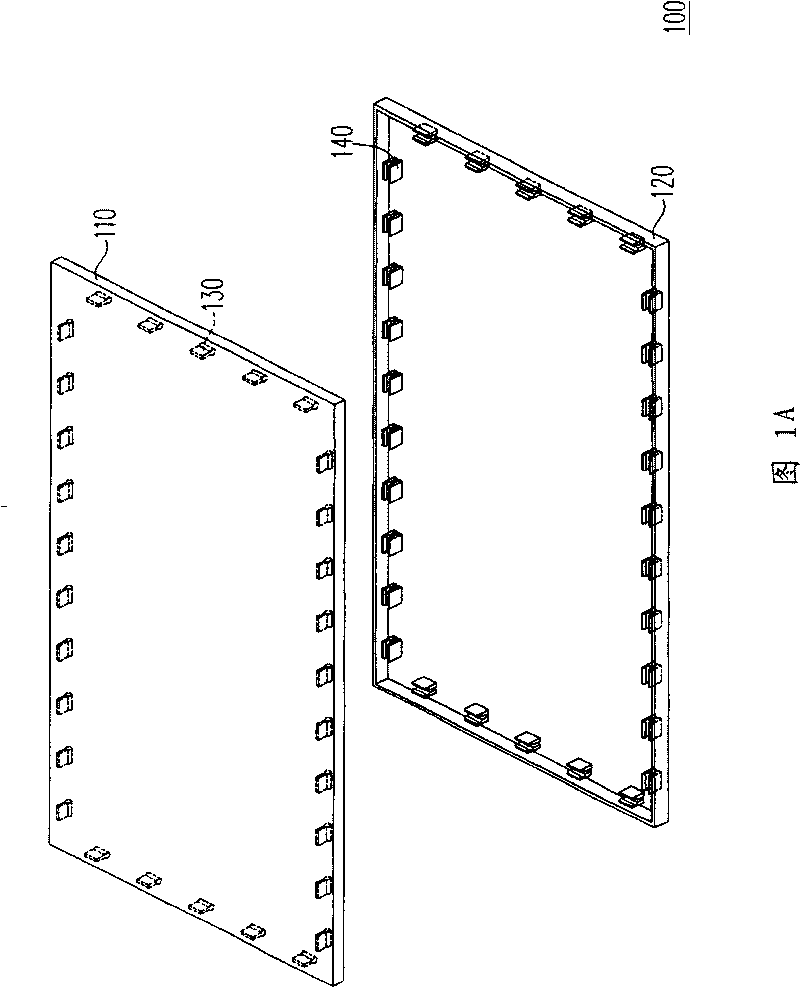
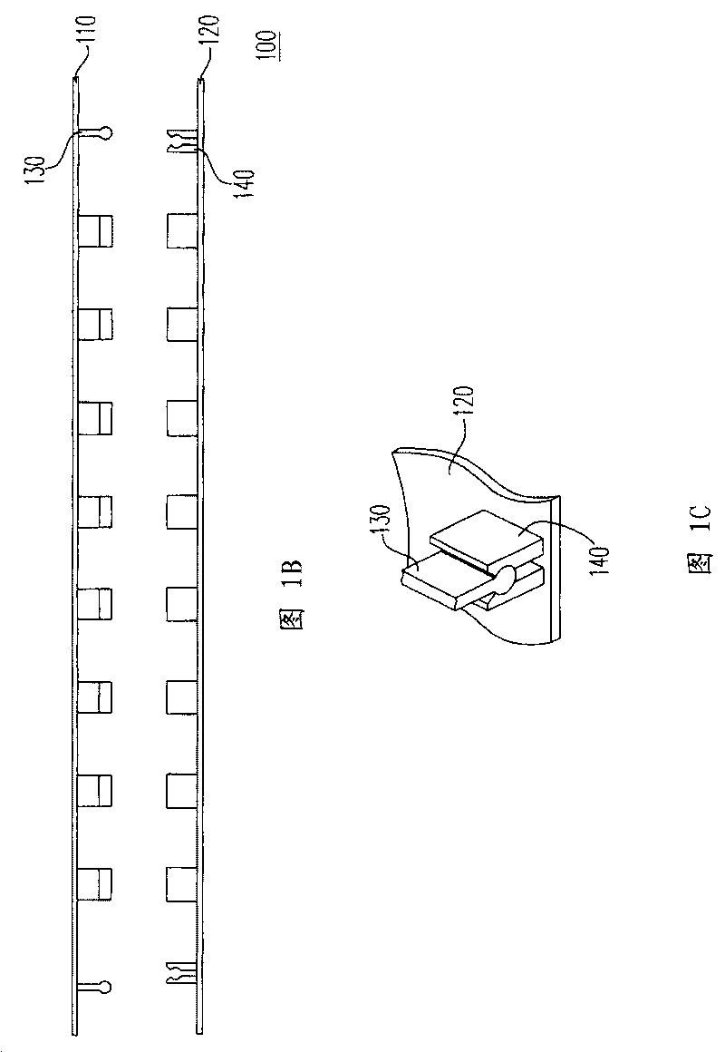
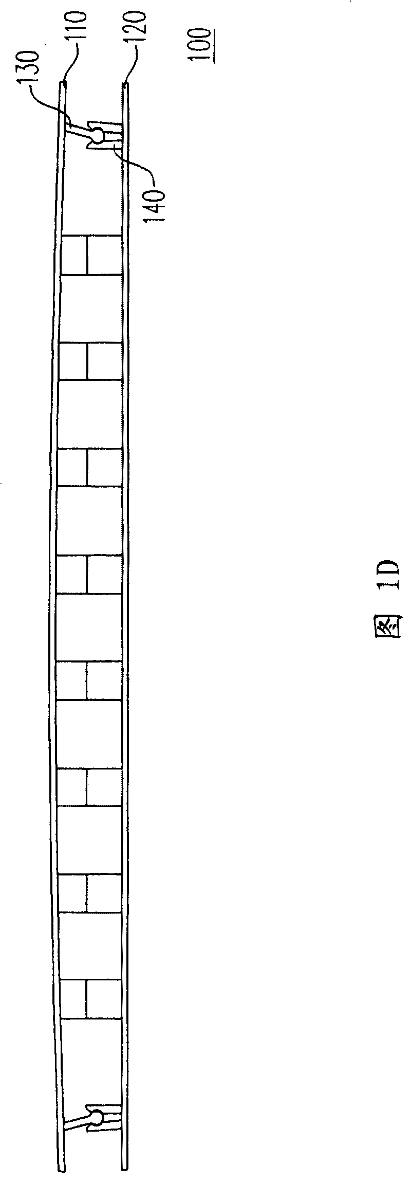
[0026] Figure 2A Shown is an exploded view of the body of an electronic device according to a preferred embodiment of the present invention, Figure 2B shown as Figure 2A side view of the body. Please also refer to Figure 2A and Figure 2B , the body 200 of this embodiment is a body of an electronic device, and the electronic device is, for example, a portable electronic device. In this embodiment, the electronic device is a notebook computer. The body 200 includes a first housing 210 , a plurality of tenon sets 220 , a second housing 230 , and a socket 240 corresponding to the plurality of tenon sets 220 . In this embodiment, the tenon set 220 is integrally formed with the first housing 210 , and the socket 240 is integrally formed with the second housing 230 , for example. In this embodiment, the first housing 210 is, for example, the upper cover of the electronic device, the second housing 230 is, for example, the lower cover of the electronic device, and the second...


PUM


Abstract

The invention relates to an electronic device body, which comprises a first case body, a plurality of blocking tenon and mortise groups, a second case body and a plurality of sockets corresponding with the blocking tenon and mortise groups. The second case body is suitable for jointing with the first case body, and the blocking tenon and mortise groups are arranged on a first surface of the firstcase body; the sockets are arranged on a second surface of the second case body, wherein, the second surface faces the first surface; furthermore, every blocking tenon and mortise group comprises at least two blocking tenons and mortises; and the arranging axes of the blocking tenons and mortises are arranged with a preset distance; and at least one blocking tenon and mortise of the blocking tenonand mortise groups are suitable for being clamped with a corresponding socket so as to fix the first case body and the second case body.

Description

technical field [0001] The present invention relates to a body, and in particular to a body of an electronic device. Background technique [0002] Generally speaking, the body of the electronic device is composed of an upper cover and a lower cover. In this way, the electronic parts arranged in the electronic device can be arranged in the inner space formed by the upper cover and the lower cover, and the body can effectively prevent the electronic parts in the electronic device from being damaged by external force, so that the electronic device can function normally. [0003] Figure 1A Shown is a known exploded view of the body, Figure 1B shown as Figure 1A side view of the body. Please also refer to Figure 1A and Figure 1B , the known body 100 includes an upper shell 110 and a lower shell 120 . In the prior art, a plurality of locking tenons 130 are disposed on the side of the inner wall of the upper casing 110 . Similarly, in the prior art, a plurality of socket...

Claims


Application Information

Patent Timeline
Patent Type & Authority Patents(China)
IPC IPC(8): H05K5/00
Inventor 张木财林家荣康兆锋
Owner ASUSTEK COMPUTER INC
Why Eureka
Try Eureka