

Hollow glass assembly capable of automatically adjusting air pressure
An automatic adjustment and hollow technology, applied in the field of vehicle doors and windows, can solve the problems of passenger safety hazards, shortened life span, increased glass thickness, etc., and achieve the effect of good appearance and reduced weight of the car body
- Summary
- Abstract
- Description
- Claims
- Application Information
AI Technical Summary
Problems solved by technology
Method used
Image

Examples
Embodiment 1
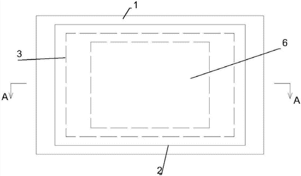
[0032] figure 1 It is a schematic plan view of the hollow glass assembly with automatic air pressure adjustment of the present invention. For the sake of simplicity, figure 1 Only the outline and position of the elastic connecting device are shown, and its specific shape is in figure 2 reflected in.
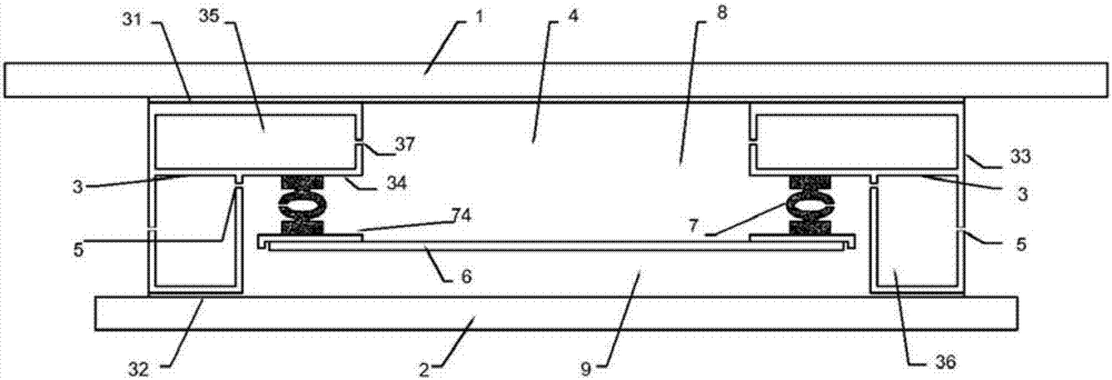
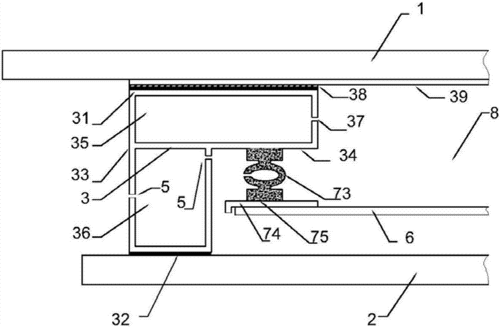
[0033] combine figure 2 and image 3 , a kind of insulating glass assembly that automatically adjusts air pressure provided by the present invention, the outer layer plate 1 is a 5mm gray glass plate, the inner layer plate 2 is a 5mm gray glass plate, the distance between the outer layer plate 1 and the inner layer plate 2 is 30mm, and the outer layer plate 1 is 5mm gray glass plate. The layer plate 1 and the inner layer plate 2 are fixedly connected by a fixed frame 3 and form a hollow chamber 4 . The fixed frame 3 is a rectangular aluminum frame with a Γ-shaped cross section, and the inside is divided into a drying chamber 35 and a filter chamber 36. The fixed frame 3 inc...
Embodiment 2
[0038] combine Figure 5 and Figure 6 Another embodiment of the present invention will be described. On the basis of Embodiment 1, the elastic connecting device 7 includes a first clamping groove 71, a second clamping groove 72, and a rubber strip 73. The first clamping groove 71 is embedded in the clamping surface 34 of the fixed frame 3, and the free frame 74 There is a second locking groove 72 and a sealing plane 75 , the first locking groove 71 and the second locking groove 72 each have a notch 711 and a slope 712 connected to the notch 711 which is easy to introduce elastic objects. The rubber strip 73 is continuously distributed along the circumferential direction of the sealing plate 6. The rubber strip 73 has a first connecting portion 731, a second connecting portion 732 and an elastic portion 733. The cross-sections of the first connecting portion 731 and the second connecting portion 732 are rectangular, The rubber vulcanization process is used to realize the air...
Embodiment 3
[0040] combine Figure 7 and Figure 8 A third embodiment of the present invention will be described. On the basis of Embodiment 1, the cross-sectional shape of the fixed frame 3 is U-shaped, and the fixed frame 3 includes an outer adhesive surface 31, an inner adhesive surface 32, a fixed surface 33 and a clamping surface 34, the outer adhesive surface 31, the inner adhesive surface The bonding surface 32 is a plane, and the fixed surface 33 is a plane along the direction of each side of the rectangular profile of the fixed frame 3. There are a drying cavity 35 and a filter cavity 36 inside the fixed frame 3, and the elastic connecting device 7 is a rubber strip 73. The rubber strip 73 is continuously distributed along the circumferential direction of the sealing plate 6. The rubber strip 73 is a hollow rubber strip with a Σ-shaped cross section, including a first connecting portion 731, a second connecting portion 732, an elastic portion 733 and a clamping portion 734. The...
PUM
 Abstract
Description
Claims
Application Information