Sealing device

A sealing device and sealing element technology, applied in the direction of engine sealing, engine components, mechanical equipment, etc., can solve the problems of uneven compression, easy leakage, loss of elasticity, etc., and achieve good sealing effect and clean and tidy equipment.

Inactive Publication Date: 2008-08-20
BAOSHAN IRON & STEEL CO LTD
View PDF1 Cites 13 Cited by
  • Summary
  • Abstract
  • Description
  • Claims
  • Application Information

AI Technical Summary

Problems solved by technology

[0003] 1) It is difficult to ensure that the sealing pressure of the gasket is equal everywhere
When the gasket is installed, it is easy to cause uneven compression at different parts of the circumference
For example, for an 8-hole flange, when tightening different bolts separately, it is difficult to ensure that the force of each bolt is the same, so it is easy to cause one side of the gasket to be tight while the other side is loose, that is to say, the gasket The sealing pressing force of different parts on the circumference is not the same, which will cause leakage, such as figure 2 shown
[0004] 2) It is difficult to ensure the size of the gasket clamping force
There is a contradiction that is difficult to solve in traditional gaskets. When the clamping force between flanges is relatively small, it is difficult to ensure that the gasket is compressed, and the sealing effect will not be achieved. If the clamping force between flanges is large, It will severely deform the gasket, lose its elasticity, and leak.
And there is a certain degree of elasticity at the beginning of the gasket, but it loses its elasticity over time and cannot play a sealing role.
Many times the gasket seals well immediately after installation, but over time the gasket loosens and leaks
[0005] 3) It cannot automatically compensate for the relative position changes of the two sealed parts within a certain degree, and it is easy to leak
It cannot automatically adapt to the conditions of each sealed part due to vibration, settlement, pad expansion and contraction, etc., and it is difficult to ensure that the sealing is still good after these conditions occur

Method used


Image

  • Sealing device
  • Sealing device
  • Sealing device

Examples


Embodiment 1

[0072] Such as Figure 4 to Figure 8 As shown, this embodiment uses the pressure of the extruded pressurized sealing ring itself and the radial elastic force of the elastic retaining ring to seal. It is mainly composed of inner and outer retaining rings and sealing rings. One of the inner and outer retaining rings is elastic. Yes, it can expand and contract when stressed, and one of the inner and outer retaining rings can be set to be elastic as required. exist Figure 4 to Figure 8 In the two cases of this method, Image 6 It is the property that the elastic ring 103 is outside, Figure 7 It is the situation that the elastic ring 105 is inside. The fixed-force inner retaining ring 101, the pressurized sealing ring 102, the elastic outer retaining ring 103, etc. are all annular. Their assembly, connection relationship, and the realization of the principle of action and purpose are as follows:

[0073] The pressure-inflating sealing ring 102 is a hollow ring like a bicycle...

Embodiment 2

[0077] Such as Figure 9 to Figure 13 As shown, this embodiment uses the pressure of the extruded pressure-filled sealing ring itself and the axial elastic force of the butterfly spring to seal. It is also mainly composed of inner and outer retaining rings and a pressure-filled sealing ring. The difference from Embodiment 1 The outer (or inner) retaining ring of this embodiment is composed of dynamic and static parts, and a butterfly spring is added to the dynamic retaining ring, so that the dynamic and static retaining ring can be set as the outer retaining ring, Such as Figure 11 as shown; it is also possible to set the dynamic and static retaining rings as inner retaining rings, such as Figure 12 shown.

[0078] by Figure 11 and Figure 9 , Figure 10 , Figure 13 For example, the pressure sealing ring 202 is installed between the inner retaining ring 201, the static outer ring 203, and the moving outer ring 204. The pressure sealing ring 202 is a hollow ring like ...

Embodiment 3

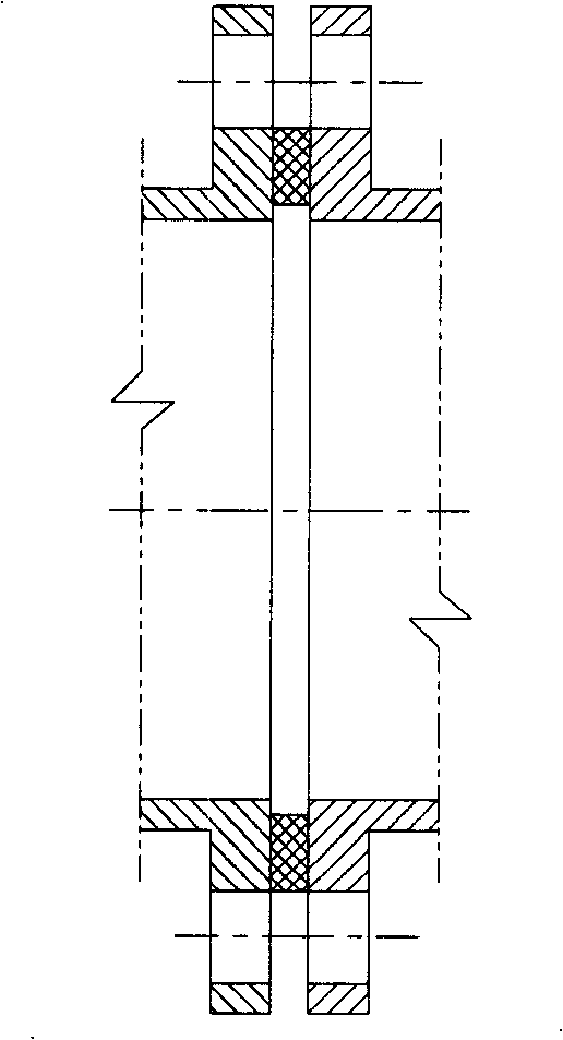
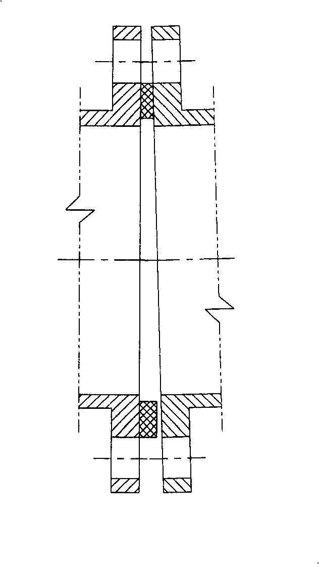
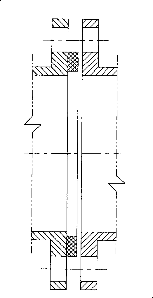
[0081] Such as Figure 14 to Figure 18 As shown, in this embodiment, the whole gasket is firstly installed between the two flanges, and after the fastening is completed, the pressure is charged, and after the pressure is charged, it is sealed. Can be filled with compressible pressurized fluid medium.

[0082] The pressure charging sealing ring 502 is installed between the inner retaining ring 501 and the outer retaining ring 503 , and after the installation and fastening is completed, the pressure charging sealing ring 502 is charged through the pressure charging pipe 504 . Fill the pressure tube 504 with clamp 506 after filling the pressure. The protection tube 505 is set outside the pressure tube 504 and connected with the outer retaining ring. The protection tube 505 is to prevent the pressure tube 504 from being deformed after being pressurized. The function of the positioning gap measuring block 507 is to be sealed on both sides of the fastening When ensuring the axial ...


PUM


Abstract

The invention relates to a sealing device which can be automatically adjusted and compensated, mainly comprising a ring-shaped sealing element which is provided with a cavity and filled with a fluid medium, an external retaining ring and an internal retaining ring which are respectively sheathed on the internal ring and the external ring of the sealing element; under free state, the sealing element is subject to the action of the external retaining ring and the internal retaining ring, and the width of the sealing device is larger than the width of the two retaining rings; wherein, the external retaining ring and the internal retaining ring are elastic retaining rings; the ring-shaped sealing element is in square shape or other irregular ring shape; the shape of the elastic retaining ringis matched with the shape of the sealing element; the ring-shaped sealing element can be replaced by a long-shaped sealing element or two communicated chambers or an inflation sac which is connected on the sealing element, etc. The invention provides the sealing device which can ensure the uniform pressing sealing at all places of the sealing device, and can ensure good sealing effect by carryingout automatic compensation according to the relative position change of the part to be sealed to a certain extent.

Description

technical field [0001] The invention relates to a sealing device, in particular to a sealing device capable of automatic adjustment and compensation. Background technique [0002] Sealing between different parts is a very common situation in the industry, and sealing gaskets are widely used in pipelines and equipment. At present, the common gaskets are: 1) asbestos gaskets, 2) rubber gaskets, 3) graphite gaskets with metal coils, and so on. Gaskets are used in a wide range of applications, such as the gasket used between the water pump casing and the water pump pump seat, the gasket used between the gearbox casing and the gearbox seat, the two flanges in the pipeline, and so on. Such as figure 1 , figure 2 , image 3 As shown, it is applied to the application of the gasket placed between the two flanges when two sections of pipeline are connected. The gasket is placed between the two flanges, and the two flanges are fastened by bolts. in, figure 1 Indicates that after...

Claims


Application Information

Patent Timeline
Patent Type & Authority Applications(China)
IPC IPC(8): F16J15/48
Inventor 程纪祥
Owner BAOSHAN IRON & STEEL CO LTD
Why Eureka
Try Eureka