Switching device

A technology for equipment and circuit breakers, applied in the field of opening and closing equipment, can solve the problems of equipment length, reduce the degree of freedom of configuration, and widen the setting space, and achieve the effect of easy transportation, maintenance and repair, and expansion of the degree of freedom of configuration

Inactive Publication Date: 2010-12-22
MITSUBISHI ELECTRIC CORP
View PDF3 Cites 0 Cited by
  • Summary
  • Abstract
  • Description
  • Claims
  • Application Information

AI Technical Summary

Problems solved by technology

In the opening and closing equipment in which the operating mechanism box is arranged at one end of the pressure vessel, although the height of the equipment (the height of the pressure vessel) is not high, the disadvantage is that the length of the equipment is long, so a wide installation space is required, and Reduced degree of freedom in configuration of other devices placed around

Method used


Image

  • Switching device
  • Switching device
  • Switching device

Examples


Embodiment approach 1

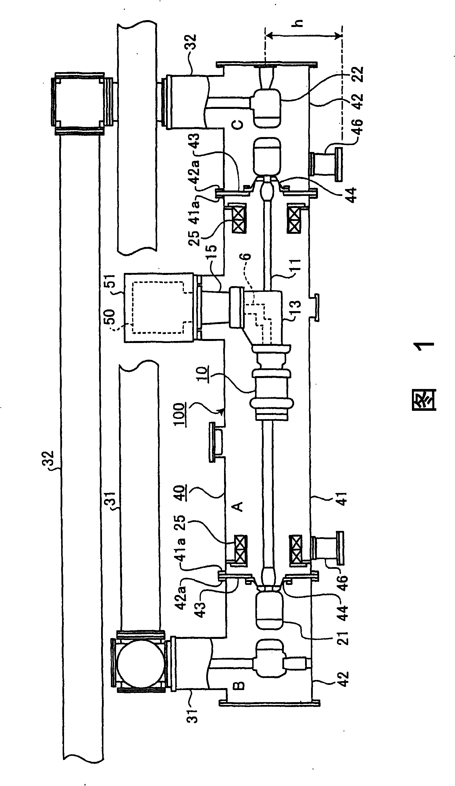
[0037] figure 1 It is a transverse sectional view showing the structure of Embodiment 1 of the switchgear of this invention. figure 2 will be figure 1 An enlarged cross-sectional view of the main part of the switchgear near the breaker is enlarged and cut away. image 3 yes figure 1 Side view of the opening and closing device. Figure 4 yes figure 1 A top view of the switchgear.

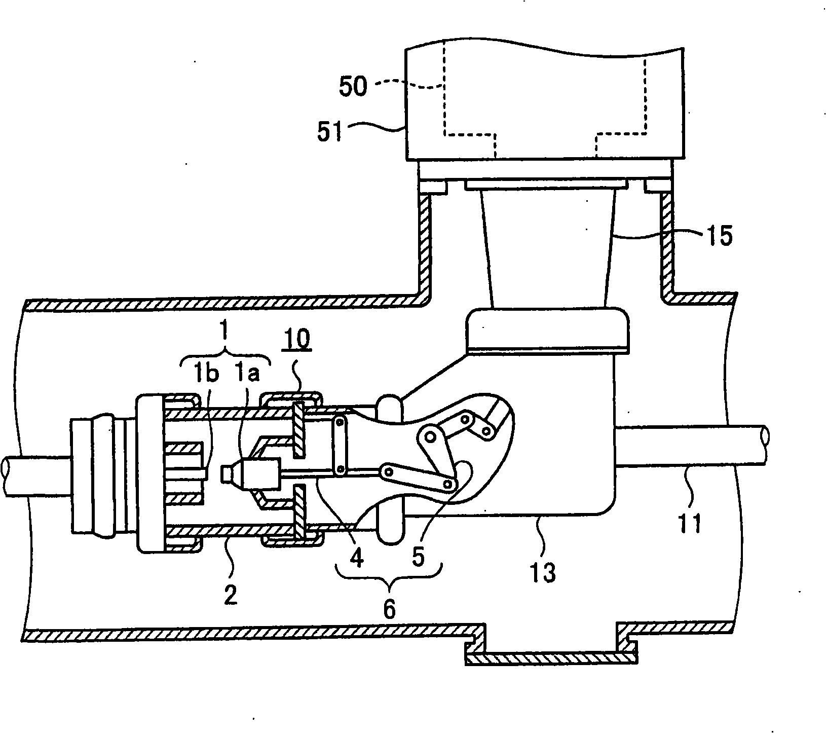
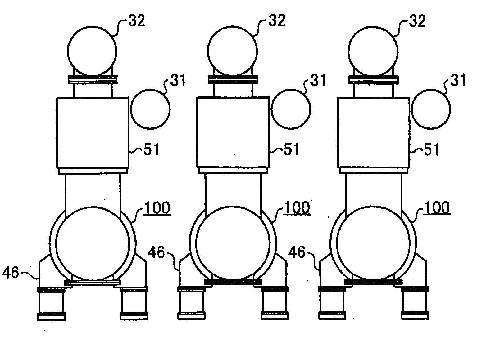
[0038] figure 1 Among them, the switchgear 100 includes: a breaker 10 installed in the center of the pressure vessel 40; The circuit breaker 21 and the second circuit breaker 22; the pressure vessel 40 for housing the circuit breaker 10 and the circuit breakers 21, 22; The operating mechanism 50 is accommodated in an operating mechanism case 51 provided on the upper portion of the pressure vessel 40 . The circuit breaker 10 and the operating mechanism 50 are connected by a connection mechanism 6 .

[0039] The pressure vessel 40 is installed at a position raised by a height h from the insta...

Embodiment approach 2

[0050] In the second embodiment, the resistance contact part connected to the resistor is connected in parallel with the main contact part to reduce the pulse at the time of restarting. Figure 5 It is a transverse sectional view showing the structure of Embodiment 2 of the switchgear of this invention. Figure 6 will be Figure 5 An enlarged cross-sectional view of the main part of the switchgear near the breaker is enlarged and cut away. Figure 5 and Figure 6 Among them, in the switchgear 100A of the present embodiment, the circuit breaker 10A has the structure of the circuit breaker 10 of the first embodiment, and the resistance contact part 3 is added thereto. The resistance contact part 3 is connected in parallel with the main contact part 1 . In addition, the resistance contact part 3 is connected in series with the resistor 9 .

[0051] Figure 6 Among them, the circuit breaker 10A is equipped with: a main contact part 1 composed of a movable main contact 1a and ...


PUM


Abstract

The invention provides an operable device that is capable of reducing an equipment height from a set face, to make transport and maintenance / repair operation easier, and increase degree of freedom for configuration of other equipment configured around, comprising a main contact part (1) (figure 2) having a moving main contact (a moving contact) (1a) and a fixed main contact (1b); a pressure vessel (40) that takes a moving direction of the moving contact (1a) as a length direction, accepts the main contact in an insulating state inside and is filled with insulating gas, to be arranged in a state that the length direction remains level; an operation mechanism (50) arranged above the pressure vessel (40), to be connected with the moving contact (1a) through a connecting mechanism (6) formed of an insulating material.

Description

technical field [0001] The invention relates to a switching device used in power systems such as power generation and transformation. Background technique [0002] Conventionally, switchgear includes a main contact portion having a fixed contact, a movable contact that contacts and separates from the fixed contact, and a pressure vessel that accommodates the main contact portion and is filled with an insulating gas. Moreover, many of these switching devices are provided with an operating mechanism that moves the movable contact forward and backward relative to the fixed contact to open and close the main contact portion. [0003] The operating mechanism is generally hydraulic, driven by an energy storage medium, and connected to the movable contact through an electrically insulated insulating control rod and a connecting rod mechanism. Furthermore, upon receiving an operation command issued during an accident of the power system, the hydraulic operating mechanism operates t...

Claims


Application Information

Patent Timeline
Patent Type & Authority Patents(China)
IPC IPC(8): H02B13/02
Inventor 小松健松田大二森智仁
Owner MITSUBISHI ELECTRIC CORP
Why Eureka
Try Eureka