Continuous catalytic reforming reactor

A catalytic reforming and reactor technology, applied in naphtha catalytic reforming and other directions, can solve problems such as sticking to the wall, difficulty, increase in volume, etc., and achieve the effects of being conducive to uniform distribution, convenient loading and unloading of catalysts, and uniform axial temperature

Inactive Publication Date: 2003-11-12
EAST CHINA UNIV OF SCI & TECH
View PDF7 Cites 36 Cited by
  • Summary
  • Abstract
  • Description
  • Claims
  • Application Information

AI Technical Summary

Problems solved by technology

[0004] The method disclosed in Chinese patent CN1258558A is that the reactant material inlet is opened on the side of the reactor shell, the vertical height of the reactant inlet center is located in the middle of the axial height of the catalytic reaction zone, and the reactant flows radially through the catalytic bed layer from outside to inside, and enters The central gas collection pipe then flows out from the bottom of the reactor, so it is difficult to control the uniform distribution of the reactant flow along the axial direction, and it is also easy to produce the phenomenon of "sticking to the wall"
In Chinese patent CN1127159A, the catalytic bed is divided by setting an intermediate wall in the catalyst bed in order to reduce the possibility of the catalyst sticking to the wall, but this method does not solve the fundamental problem of the catalyst sticking to the wall, but leads to a complex reactor structure
[0005] To sum up, as mentioned in the above patents, most of the radial reactors of various catalytic moving beds adopt the method that the reaction materials flow from the outside to the inside along the radial direction, and the radial gas shows an acceleration trend, and the reforming reaction is a process of increasing volume. , therefore, in order to avoid "sticking to the wall", it brings great restrictions and difficulties to the design of the moving bed radial reactor
At the same time, the centripetal flow from the outside to the inside of the existing patented technology will inevitably cause the axial temperature difference of the catalytic bed due to the heat loss of the imported material in the outer split flow channel.

Method used


Image

  • Continuous catalytic reforming reactor
  • Continuous catalytic reforming reactor
  • Continuous catalytic reforming reactor

Examples


Embodiment Construction

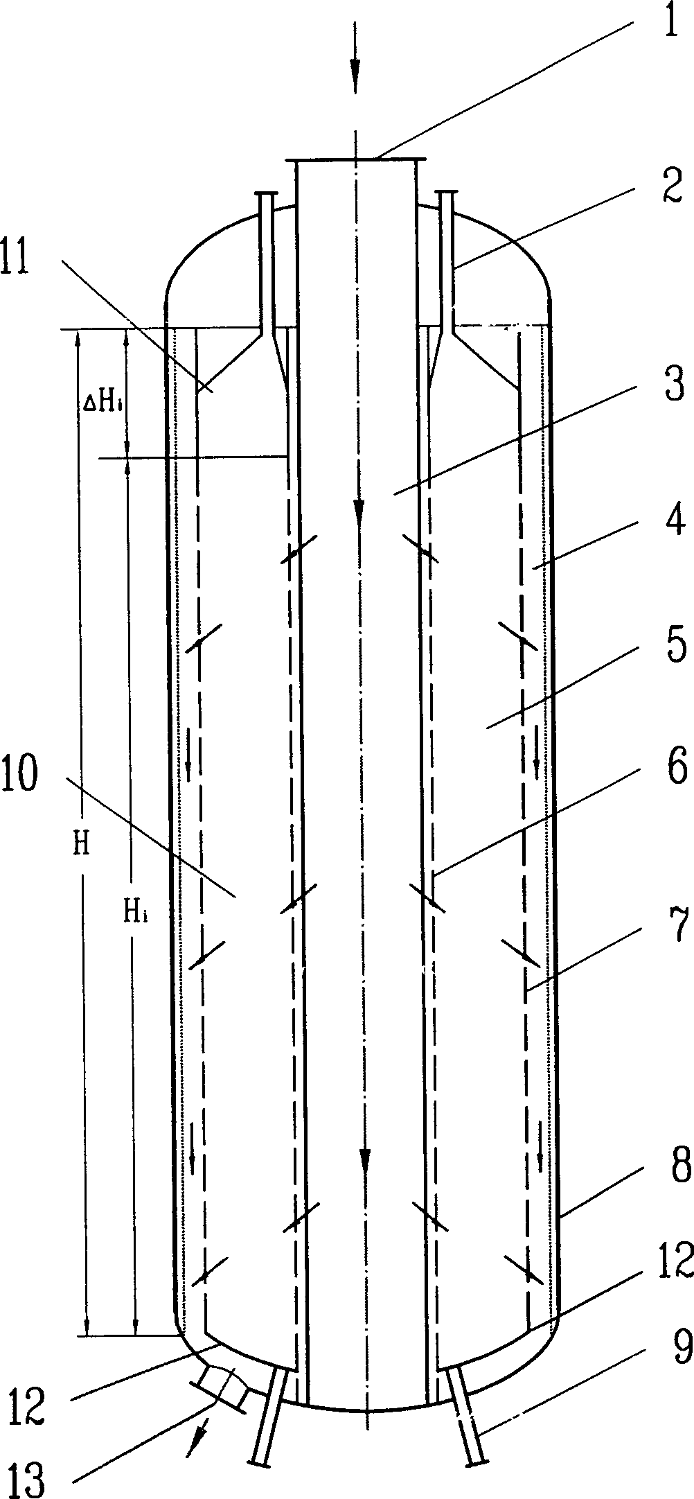
[0031] figure 1 The described reactor works like this:

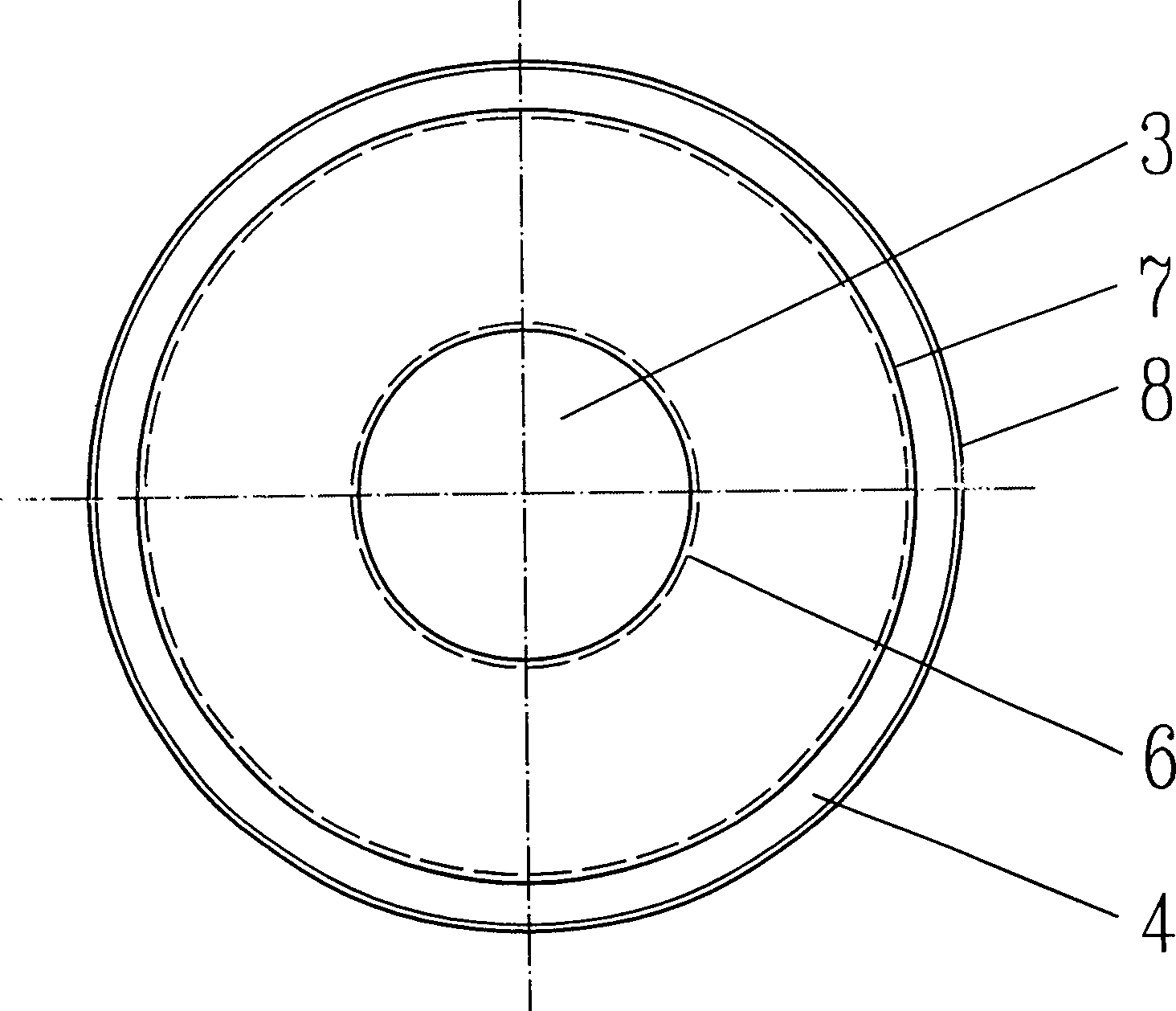
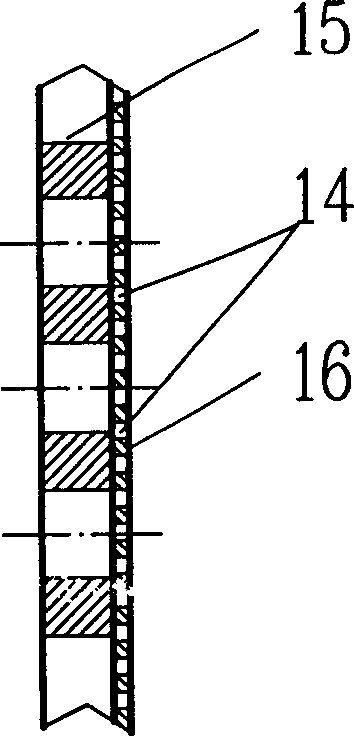
[0032] The molar ratio of hydrogen to hydrocarbon in the raw material is 1-3, the reaction temperature is 420-580°C, the reaction pressure is 0.2-0.8Mpa, and the weight space velocity is 0.5-2.5 hours -1 ,exist figure 1 The flow of the reaction material in the reactor shown is as follows: the reaction material enters the split flow channel 3 formed by the porous wall inner cylinder 6 from the reaction material inlet 1, and flows radially into the catalytic bed 10 through the distribution holes 14 on the porous wall inner cylinder 6 to carry out reaction, and then the reaction product enters the reaction product collecting flow channel 4 through the distribution hole 14 on the porous outer wall 7 from inside to outside, and flows out through the reaction product outlet 13 . After the catalyst particles flow into the catalyst bed from the catalyst feed pipe 2, they move axially from top to bottom, and then flow out of th...


PUM

PropertyMeasurementUnit
porosityaaaaaaaaaa
porosityaaaaaaaaaa
porosityaaaaaaaaaa

Abstract

The present invention discloses a continuous catalytic reforming moving bed radial reactor. Said reactor adopts a circular container with catalytic bed as reaction equipment, the reactant inlet is positioned in the upper end of said reaction equipment, and its outlet is positioned in lower end of said reaction equipment, said catalytic bed is formed from external porous wall and internal porous wall cylinder in which the catalyst is filled. Said catalyst can be continuously flowed from top to bottom by means of gravity, at the same time the reaction material can be centrifugally flowed from centre toward exterior in the reaction equipment, and can be concurrently flowed from top to bottom in the distributary channel and collecting channel. Said invention is a Z-type centrifugal radial moving bed reactor, and its structure is simple and catalyst utilization rate is high.

Description

technical field [0001] The invention relates to a gas-solid phase catalytic moving bed radial reactor suitable for medium and low pressure or normal pressure, in particular to a catalytic moving bed radial reactor suitable for hydrocarbon catalytic reforming. Background technique [0002] In the existing hydrocarbon catalytic reforming method, a gas-solid phase moving bed radial catalytic reactor is generally used. The gas-solid phase moving bed radial reactor is generally composed of an upper head, a cylindrical side wall and a bottom head to form the outer shell of the reactor. In the reactor, there is a cylindrical outer porous cylinder and a cylinder. The annular space formed by the porous cylinder inside the shape forms a cylindrical catalyst bed after the catalyst is loaded. The cylindrical inner porous cylinder can prevent catalyst particles from entering the inner space of the inner porous cylinder, and at the same time it can be used as a gas distribution pipe and ...

Claims


Application Information

Patent Timeline
Patent Type & Authority Applications(China)
IPC IPC(8): C10G35/04
Inventor 朱子彬朱学栋李瑞江俞丰吴勇强徐志刚张成芳
Owner EAST CHINA UNIV OF SCI & TECH
Why Eureka
Try Eureka