Undersea well product transport

a technology for product transportation and sub-sea wells, applied in the direction of sealing/packing, wellbore/well accessories, insulation, etc., can solve the problems of large cost of large surface facilities for processing warm production, inability to maintain wellhead production temperature without accruing expensive pipeline heating and/or insulation costs, and inability to meet the needs of large-scale production, etc., to achieve short period of time, reduce the size and expense, and reduce the size of such equipmen

Inactive Publication Date: 2006-08-10
BENSON ROBERT A
View PDF27 Cites 77 Cited by
  • Summary
  • Abstract
  • Description
  • Claims
  • Application Information

AI Technical Summary

Benefits of technology

[0007] There is a need for an apparatus to eliminate the need for heated pipe well effluent transport, to eliminate or minimize the need for large floating structures, to eliminate or reduce the need for sub-sea processing equipment, to reduce the costs associated with transporting well product to shore, and / or to eliminate or reduce the need for chemical additions to production flow.
[0019] Conventional sub-sea production wells target large or very high production rate capable reservoirs, which generally require or utilize large diameter wells, casings, completion systems, and the like, to generate maximum production rates for a given well and field over a relatively short period of time. The present invention can reduce the size and expense of much of such down-hole and sub-surface equipment by standardizing and reducing the size of such equipment to match closely the size and capacity of downstream components of the apparatus. Reservoir pressure is maintained over longer periods of time by the use of the apparatus for extraction of hydrocarbon well product. Furthermore, slower, steadier product withdrawal from the formation enables better natural re-pressurization through the existing geological structure of the formation. Likewise, the slower well production rate and concomitant withdrawing can reduce formation plugging and / or deterioration. The apparatus of the present invention can extend the producing life of a hydrocarbon reservoir and recover a high percentage of the reservoir's liquid hydrocarbon capacity relative to current conventional drilling and processing practices.
[0020] Conventional undersea flowlines generally move products processed or unprocessed as fast as practicable to prevent cooling, to drain a reservoir as rapidly as possible for immediate economic return and to minimize the size and resultant cost of pipeline. Frequently, current flowline rates exceed five feet per second velocity and often are at much higher velocity. High pressures are generally required. Wear and failure risk can be very high. The present invention considerably reduces the flow velocity in long flowlines, thus reducing wear and failure risk.

Problems solved by technology

However, for oil and / or gas wells in deeper water, often far off-shore, the constant cooling effect of ocean water makes it difficult to maintain wellhead production temperatures without accruing expensive pipeline heating and / or insulating costs.
As such, production from such sub-sea wells becomes economically unfeasible, especially for smaller reservoirs.
Likewise, the cost of large surface facilities for processing warm production is substantial in deep water and can generally only be justified for relatively large hydrocarbon reservoirs.
In addition, heating of a cooler flow using equipment on a floating structure is substantially more costly than heating the flow at a shore-based facility.
Floating structures in deep water and fixed structures in relatively shallow water are subject to the surface effects of storms and other natural events.
Production risers to surface structures are likewise more subject to natural and intentional trauma.
In addition, conventional structures are subject to accidental, or in rare cases intentional, damage by surface vessels, or the like.
Generally, such floating structures are large and incur relatively substantial expense to drill, complete, work-over, process, and the like for such wells.
Relative to shore-based facilities, floating structures are significantly more costly to operate on a per square foot basis or per unit weight basis.
The additional cost, requirements of storage, and requirements for injection means of such chemicals, as well as removal of such chemicals during processing, can also add considerable expense to production.
Some of the overall efficiencies and cost reductions of the inventive system may not be as attainable with sea-based processing structures.
Wear and failure risk can be very high.

Method used


Image

  • Undersea well product transport
  • Undersea well product transport
  • Undersea well product transport

Examples


Embodiment Construction

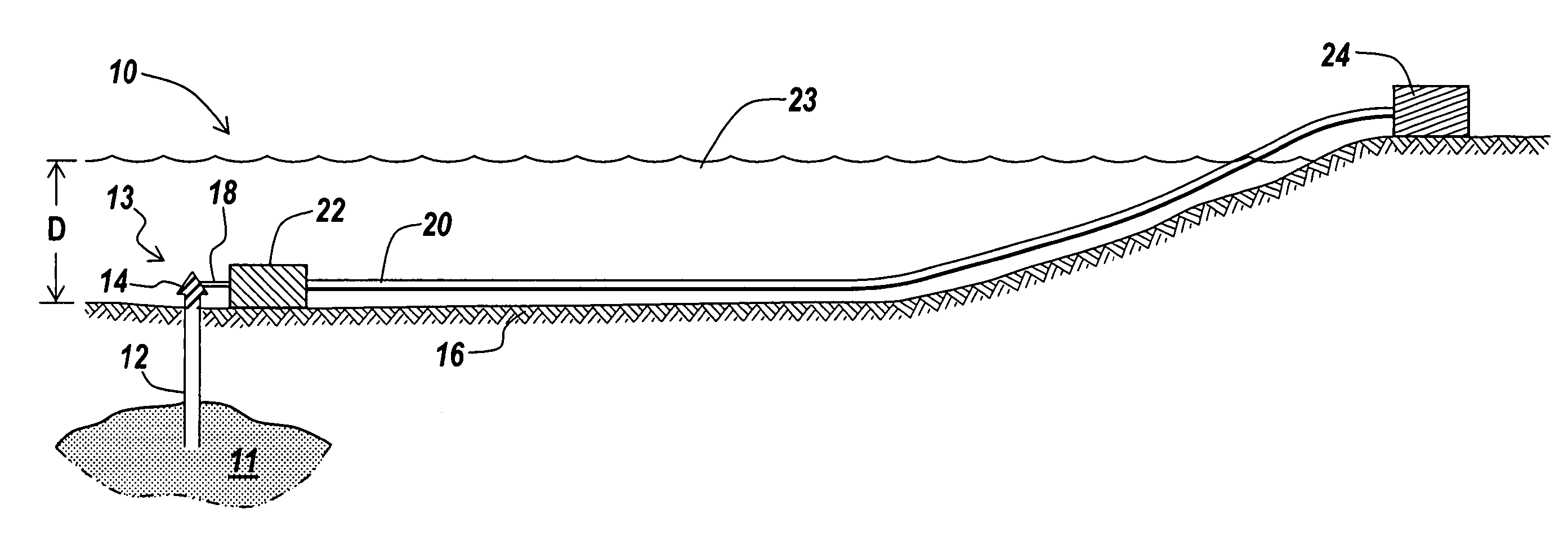
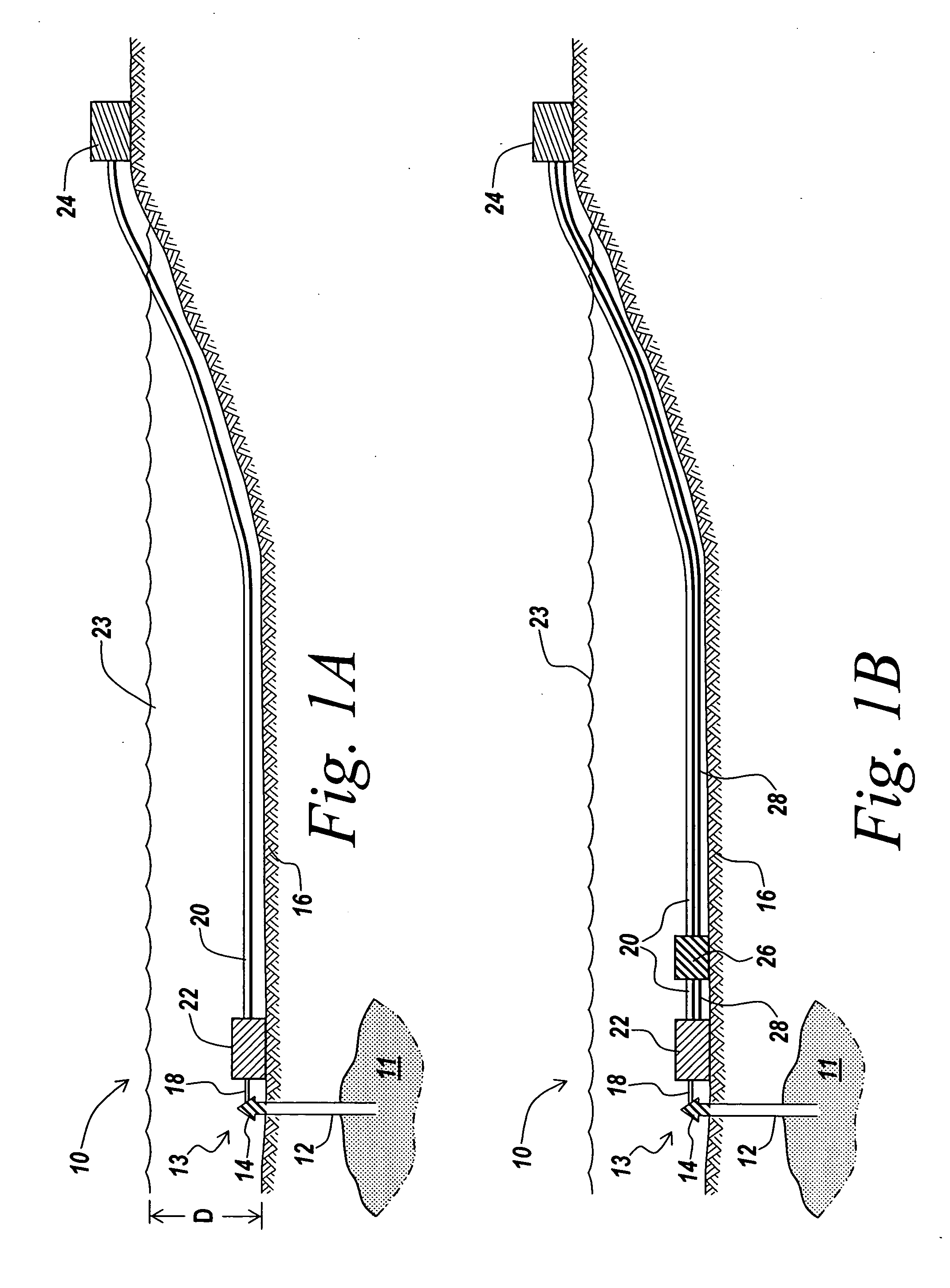
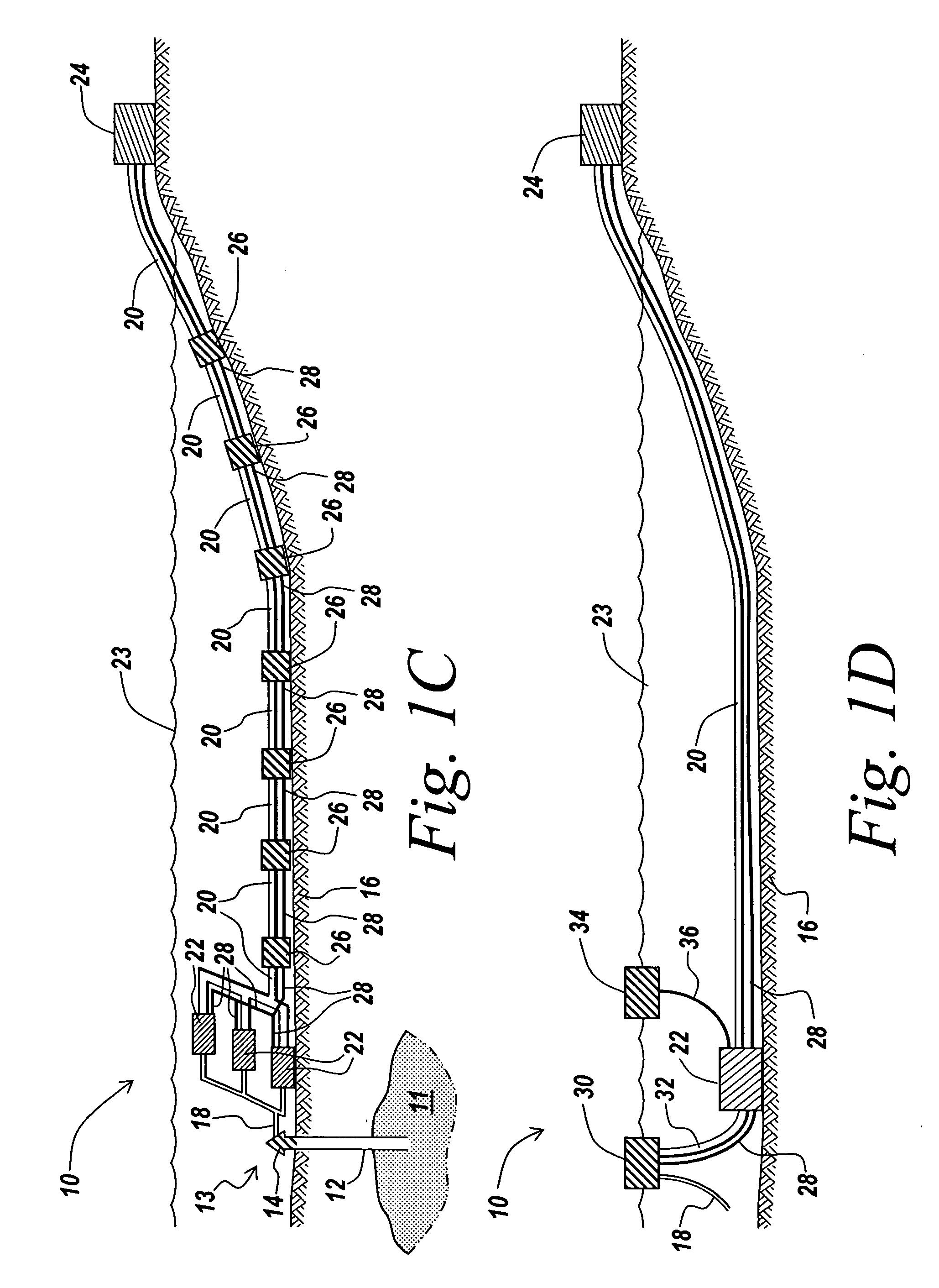
[0038] An illustrative embodiment of the present invention relates to an apparatus for the undersea capture and transport of hydrocarbon well product (i.e., oil, gas, and the like) in a cost effective and efficient manner. In practice, hot production from a sub-sea well passes at an optimum pressure and flow rate into a non-plugging cold flow generator. This enables a cooled stable mass of the produced material in a dispersed mixture (typically with the oil acting as the carrier) exiting the cold flow generator to move slowly at optimum pressures through very long submerged pipe lines upward across the shallowing sea bottom to a shore based, and thereby more cost efficient, processing facility. At the shore based, or near-shore based processing facility, the cold dispersed mixture is processed into valuable products primarily crude oil, and its useful derivatives. The apparatus of the present invention eliminates the need for, or reduces the size of, many expensive, trauma prone flo...


PUM

PropertyMeasurementUnit
temperatureaaaaaaaaaa
pressureaaaaaaaaaa
velocityaaaaaaaaaa

Abstract

An apparatus and corresponding method of use extracts, cools, and transports effluents from subterranean, sub-sea oil formations to distant shore based processing facilities. The effluents, mostly crude oil, are conveyed rapidly to a cold flow generator near the oil wellhead on the sea bottom using the cold seawater to chill the effluents to a dispersed mixture including generated solids. The mixture is transported close to sea bottom temperatures, slowly, with small pressure drops, in low-cost submerged bare pipes over long distances to on or near shore processing facilities that can produce useful hydrocarbon products more cost effectively than at sea processing facilities. The apparatus eliminates or minimizes the need for heated or insulated pipe, the need for large floating processing structures, the need for sub-sea processing equipment, and / or the need for chemical additions to production flow.

Description

RELATED APPLICATIONS [0001] This application claims priority to, and the benefit of, co-pending U.S. Provisional Application 60 / 703961, filed Jul. 29, 2005, for all subject matter common to both applications. The disclosure of said provisional application is hereby incorporated by reference in its entirety.FIELD OF THE INVENTION [0002] The present invention relates to an apparatus suitable for connecting to an undersea well, converting the well's effluents to a cold dispersed mixture by means of a cold flow generator, and transporting such mixture of effluents by means of long conduits to an effluents processing facility, preferably on or close to shore. BACKGROUND OF THE INVENTION [0003] Generally, sub-sea hydrocarbon production is maintained at or near wellhead production temperature for ease of transport and processing. However, for oil and / or gas wells in deeper water, often far off-shore, the constant cooling effect of ocean water makes it difficult to maintain wellhead product...

Claims


Application Information

Patent Timeline
Patent Type & Authority Applications(United States)
IPC IPC(8): E21B33/037
CPCE21B17/01E21B36/001E21B43/017F17D1/16
Inventor BENSON, ROBERT A.
Owner BENSON ROBERT A
Why Eureka
Try Eureka