Downhole filter

a filter and filter body technology, applied in the field of downhole filters, can solve the problems of affecting the formation itself, affecting the operation of the filter body, so as to simplify the manufacture of the expandable filter arrangement and minimize the risk of tearing

Inactive Publication Date: 2007-03-13
WEATHERFORD TECH HLDG LLC
View PDF913 Cites 84 Cited by
  • Summary
  • Abstract
  • Description
  • Claims
  • Application Information

AI Technical Summary

Benefits of technology

[0014]The form of openings present in the walls of tubular members in accordance with these embodiments of the present invention is of course unlike the form of openings that would be achieved if a normally apertured planar sheet, in which openings have parallel walls, is rolled into a tubular form, which tends to create openings in which the inner width of the openings is less than the outer width. Furthermore, conventional slotted liner, made of oilfield pipe that has been longitudinally slotted with a precision saw or mill, will feature parallel side walls and will tend to have an outer length greater than an inner length. Thus this aspect of the invention provides the preferred form of openings for sand exclusion such as is achieved in wire-wrapped screens, but without the complexity and expense associated with wire-wrapped screens, and in a relatively robust form.
[0021]Existing tubular members are slotted to create filters using a precision saw or mill. The use of a precision cutting tool is necessary to provide the accurately controlled slot width required to provide an effective filter with predictable sand control properties. However, the applicant has now achieved the previously unattainable accuracy required of filter slots or openings by laser-cutting. Conventionally, a slot cut by laser has a larger width at the slot ends, where cutting commenced and stopped, producing “dog-bone” slots, which are of little if any utility in filter applications. A conventional laser cutting operation utilises a substantially constant laser energy input, and when cutting commences the laser is held stationary relative to the workpiece until the laser has cut through the depth of the metal, before moving along the workpiece to cut the slot, and then coming to a stop at the end of the slot. Applicant believes that, without wishing to be bound by theory, where the laser is held stationary relative to the workpiece, energy transfer to the workpiece from the laser creates a pool of molten metal surrounding the area of metal which is removed by vaporisation, and this pool of molten metal is removed from the workpiece with the vaporised metal. This has the effect that the width of cut is increased relative to areas where the laser is moving relative to the workpiece, and where less metal is removed by this mechanism. The applicant has found that it is possible to avoid this problem by controlling the laser energy during the cutting process, and more particularly by reducing the laser energy when the laser is stationary relative to the workpiece. By doing so it has been possible to cut slots of consistent width, suitable for use in filtering applications. Other techniques may be utilised to control slot width, including reducing the flow rate of purging gas, and thus reducing the rate of removal of molten metal. Alternatively, or additionally, a pulsed laser may be used, which laser produces discrete energy pulses such that, in use, a laser spot is not focussed on the workpiece for a time which is sufficient to allow thermal energy to be conducted into the metal surrounding the cutting zone.
[0022]There are a number of advantages gained by utilising laser to cut the perforations. Firstly, the perforations may be of forms other than those achievable by means of a conventional rotating cutting tool, and in particular it is possible to cut narrow slots of a serpentine form. Secondly, laser cutting tools may operate in conjunction with a gas purge, which carries away the vaporised and molten metal, and cools the surrounding material. An oxygen purge may be utilised to help the exothermic reaction at high temperatures, but for the present application an inert gas purge is preferred. However, in addition to merely cooling the metal, the gas purge jet has been found to produce a quenching effect at the edges of the cut, tending to increase the hardness of the metal surrounding the cut, particularly the outer edges of the perforations. Of course this is the area of the perforation which is likely to have to withstand the greatest erosion.
[0024]Surprisingly, it has been found that relatively thin laser-perforated metal filter sheet may be deformed, and in particular extended, with minimal risk of tearing. It has been found that the perforations, which are typically originally substantially circular, tend to deform on diametric expansion of the filter sheet to assume the form of elongate slots of width less than the diameter of the original perforations.
[0025]Laser-cut perforations tend to have a keystone or trapezoidal section, and the filter sheet is preferably arranged such that the smaller diameter end of each perforation in the filter sheet is adjacent the outer face of the sheet. It has been found that the laser-perforated sheet is sufficiently robust to obviate the requirement to provide a protective shroud around the exterior of the sheet, thus simplifying the manufacture of the expandable filter arrangement and allowing installation of the laser-perforated sheet within the wellbore without the tear-prone protective shroud. The laser-perforated sheet may be initially provided in planar form, and then wrapped or otherwise formed around the base tube. The edges of the sheet may be joined by any convenient method, such as a seam weld.

Problems solved by technology

The presence of sand in the production fluid can lead to blockages, premature wear and damage to valves, pumps and the like.
Produced sand which has been separated from the produced fluid at surface requires storage and disposal, which can be difficult and expensive, particularly in offshore operations.
Furthermore, unchecked production of sand from a formation can result in substantial damage to the formation itself.
Such liner is relatively inexpensive, and is accordingly preferred for wells having long completion intervals, but does not have high-inlet-flow areas, and may therefore be unsuitable for high-rate wells.
While such expandable filter arrangements have been used successfully on many occasions, manufacture of the arrangements is relatively difficult and expensive, and the location and relative movement of the filter sheets during the expansion process introduces a risk of the filter sheets tearing.
When installing the sand control device as a completion string within the wellbore, the outer shroud may tear upon coming into contact with an obstruction within the wellbore, rendering the sand control device ineffective for its desired purpose.
Installing a filter arrangement downhole is especially problematic when it is desired to drill to the desired depth within the formation using the filter arrangement, as the outer shroud is especially prone to tearing upon portions of the formation while drilling.

Method used


Image

  • Downhole filter
  • Downhole filter
  • Downhole filter

Examples


Embodiment Construction

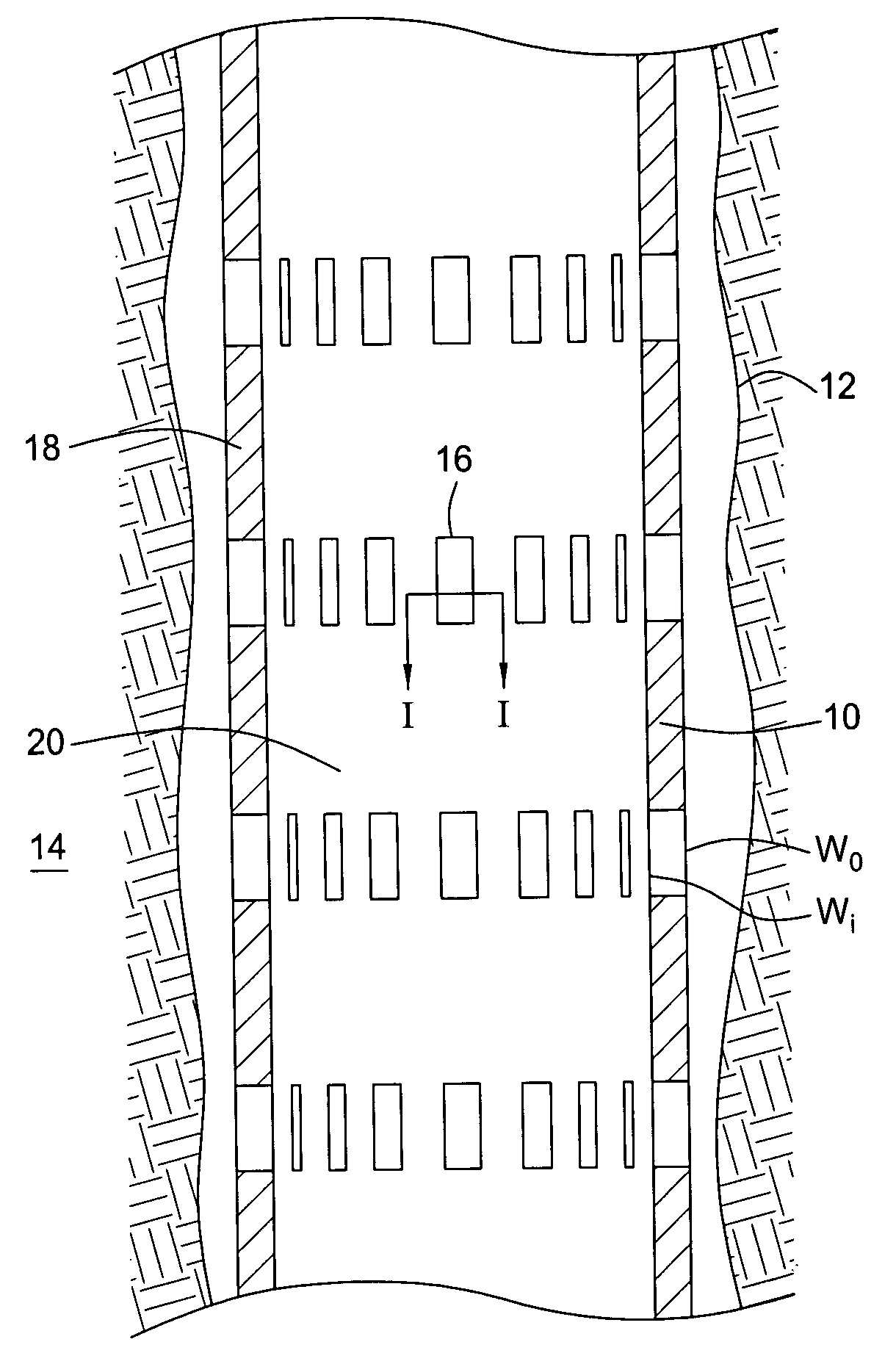
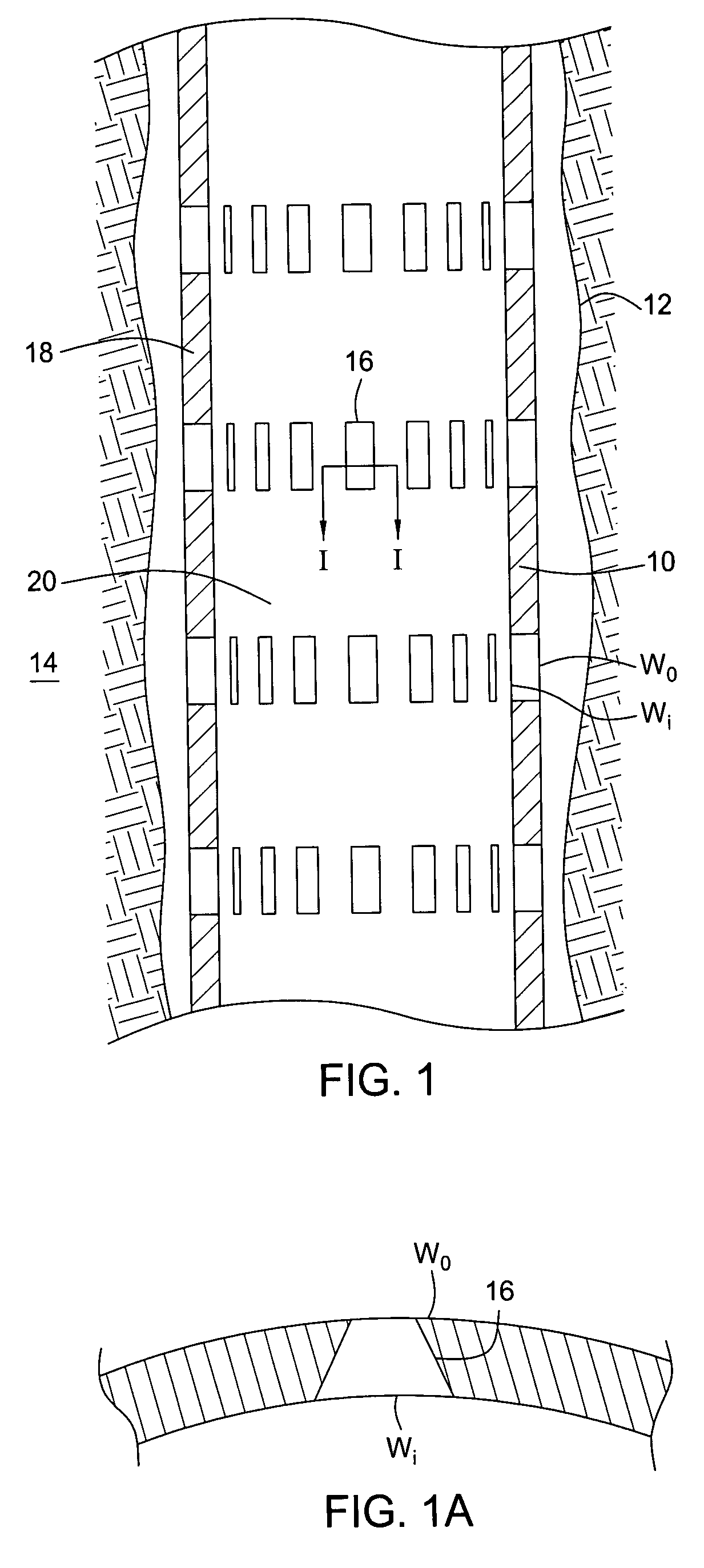
[0038]Reference is first made to FIG. 1 of the drawings, which is a schematic sectional view of a sand control device in the form of downhole filter 10, in accordance with an embodiment of an aspect of the present invention. The filter 10 is shown located in a wellbore 12 which has been drilled from surface to intersect a sand-producing hydrocarbon-bearing formation 14.

[0039]The filter 10 comprises a metal tubular in which a large number of longitudinally-extending slots 16 have been cut. The slots 16 have a keystone or trapezoidal form, that is the width of the slots increases from the exterior of the tubular wall W0 to the interior W1. This feature is shown in FIG. 1a, which is an enlarged sectional view of a slot 16 through line I—I of FIG. 1. As shown, the inner slot width W1 is greater than the outer slot width W0. The outer, minimum width W0 is selected to be smaller than the diameter of the particulates it is desired to prevent from passing from the formation 14, through the ...


PUM

PropertyMeasurementUnit
inner diameteraaaaaaaaaa
outer widthaaaaaaaaaa
inner widthaaaaaaaaaa

Abstract

A downhole filter comprises a tubular member having a wall defining a plurality of openings. The openings have an outer width less than an inner width. The parts of the opening defining the smaller width are defined by radially outer parts of the openings, such that particulates or sand prevented from passing through the openings will tend to be retained to the outside of the tubular member. A method comprises providing a tubular string having a non-porous tubular portion and a porous tubular portion, and installing the tubular string within a wellbore such that the porous tubular portion is located adjacent a fluid-producing formation within the wellbore. In another embodiment, an apparatus comprises a drill string comprising a non-porous tubular portion and a porous tubular portion, and an earth removal member operatively connected to a lower end of the drill string.

Description

CROSS-REFERENCE TO RELATED APPLICATIONS[0001]This application is a continuation-in-part of U.S. patent application Ser. No. 10 / 693,185 filed Oct. 24, 2003 now U.S. Pat. No. 7,093,653, which is herein incorporated by reference in its entirety. U.S. patent application Ser. No. 10 / 693,185 claims benefit of Great Britain Patent Application No. 0224807.8 filed Oct. 25, 2002, which is also herein incorporated by reference in its entirety.[0002]This application is also a continuation-in-part of U.S. patent application Ser. No. 10 / 853,498 filed on May 25, 2004, which is herein incorporated by reference in its entirety. U.S. patent application Ser. No. 10 / 853,498 is a continuation of U.S. patent application Ser. No. 10 / 364,718 filed on Feb. 11, 2003, now U.S. Pat. No. 6,742,606, which is herein incorporated by reference in its entirety. U.S. patent application Ser. No. 10 / 364,718 is a continuation of U.S. patent application Ser. No. 09 / 469,643 filed on Dec. 22, 1999, now U.S. Pat. No. 6,543,...

Claims


Application Information

Patent Timeline
Patent Type & Authority Patents(United States)
IPC IPC(8): E21B43/10B21D17/04B21D39/04B21D39/10E21B7/00E21B7/20E21B29/00E21B29/10E21B33/138E21B33/16E21B43/00E21B43/08
CPCB21D17/04E21B43/108B21D39/10E21B7/00E21B7/20E21B29/00E21B29/005E21B29/10E21B33/138E21B33/16E21B43/00E21B43/086E21B43/103E21B43/105B21D39/04
Inventor RUDD, WAYNEMETCALFE, PAUL DAVID
Owner WEATHERFORD TECH HLDG LLC
Why Eureka
Try Eureka