Ultrasonic diagnostic apparatus

a diagnostic apparatus and ultrasonic technology, applied in diagnostics, medical science, angiography, etc., can solve the problems that the motion velocity of living tissue cannot be detected by the doppler technique, and the ultrasonic echo should not produce a doppler effect, so as to achieve high computing performance, measure the elasticity accurately, and avoid significant computational complexity.

Inactive Publication Date: 2009-01-08
PANASONIC CORP
View PDF4 Cites 29 Cited by
  • Summary
  • Abstract
  • Description
  • Claims
  • Application Information

AI Technical Summary

Benefits of technology

[0039]According to the present invention, an ultrasonic echo signal for calculating a thickness variation or elasticity between measuring points based on the axial velocity of an arterial wall tissue is selected every frame period. The motion velocity at each measuring point may be calculated as in the conventional method using the selected ultrasonic beam. As a result, the shape property or the qualitative property of an organism's arterial tissue can be evaluated accurately without significantly increasing the computational complexity. That is why there is no need to use a computing circuit with high computing performance for an ultrasonic diagnostic apparatus. Consequently, an ultrasonic diagnostic apparatus that can measure the elasticity accurately can be provided at a reduced cost.

Problems solved by technology

However, no Doppler effect should be produced in an ultrasonic echo that has been reflected perpendicularly to the direction in which the living tissue is moving, which is a problem.
In other words, the motion velocity of the living tissue cannot be detected by the Doppler technique perpendicularly to the ultrasonic echo.

Method used


Image

  • Ultrasonic diagnostic apparatus
  • Ultrasonic diagnostic apparatus
  • Ultrasonic diagnostic apparatus

Examples


embodiment 1

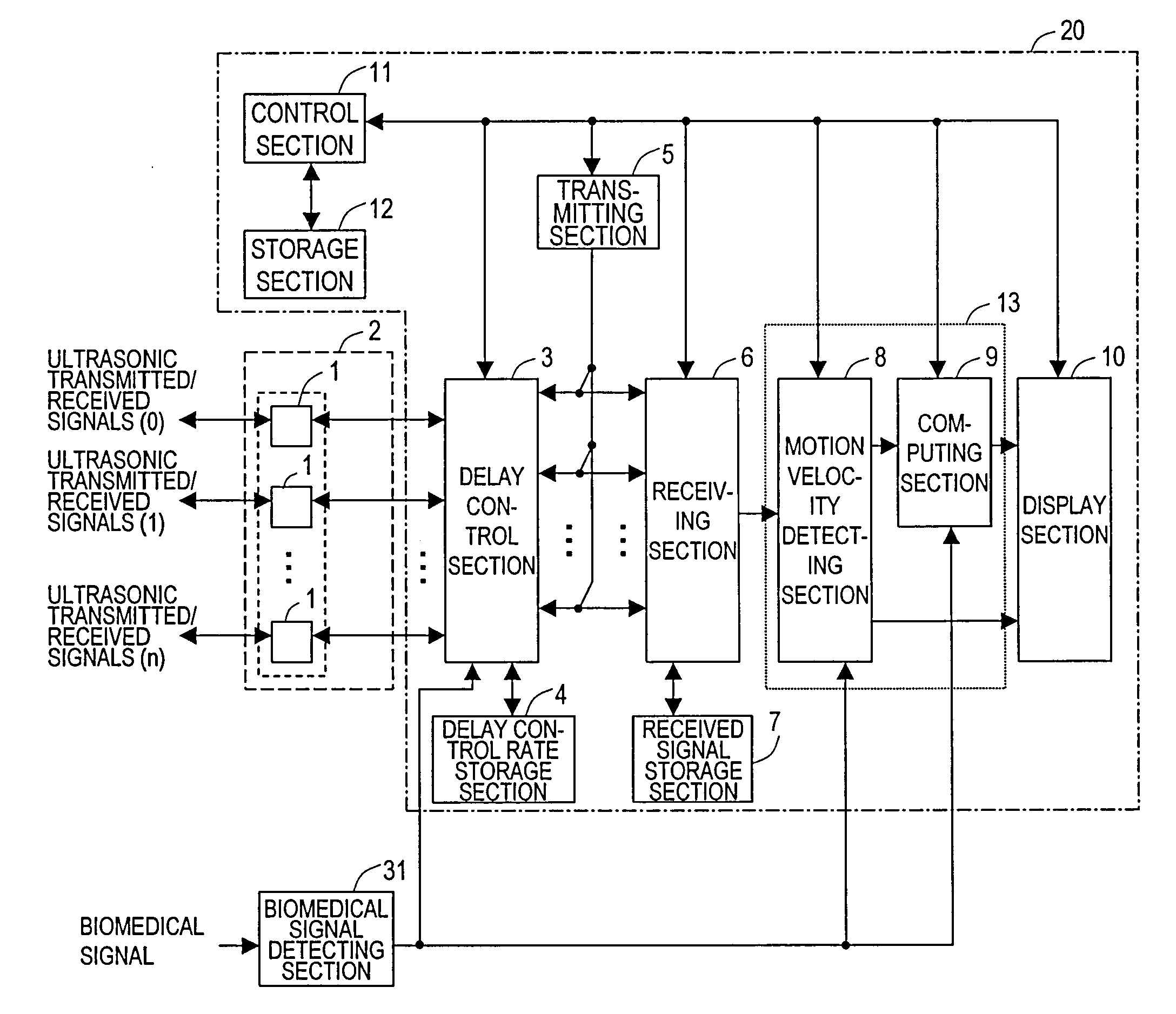
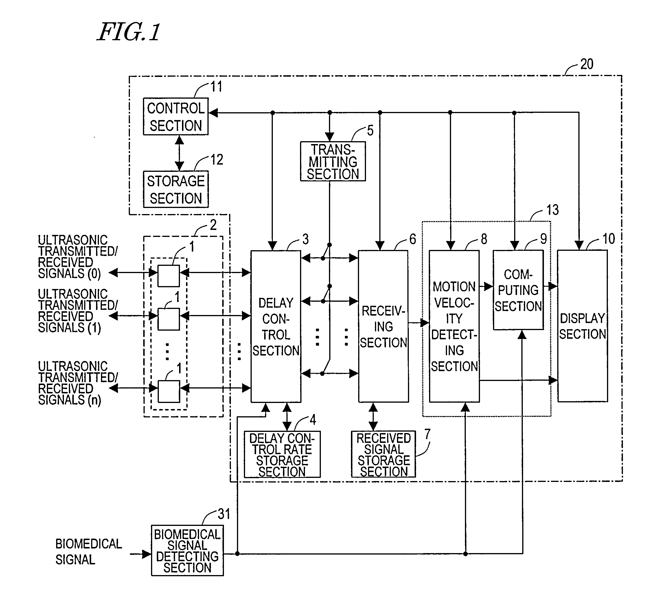
[0079]Hereinafter, a First Preferred Embodiment of an ultrasonic diagnostic apparatus according to the present invention will be described with reference to the accompanying drawings. FIG. 1 is a block diagram of an ultrasonic diagnostic apparatus 20. The ultrasonic diagnostic apparatus 20 evaluates either a shape property or a qualitative property of an organism using an ultrasonic probe 2. The apparatus 20 can be used particularly effectively to measure the elasticity of an arterial wall tissue of an organism, among other things. As used herein, a “shape property” of an organism may refer to either the shape of a living tissue or the motion velocity of the living tissue due to a variation in its shape with time, the magnitude of its displacement, which is an integrated value thereof, and a variation in thickness between two points that have been set on the living tissue. On the other hand, a “qualitative property” of an organism will refer herein to the elasticity of the living ti...

embodiment 2

[0129]Hereinafter, a second preferred embodiment of an ultrasonic diagnostic apparatus according to the present invention will be described with reference to the accompanying drawings. The ultrasonic diagnostic apparatus21 of this preferred embodiment detects either the axial velocity or the magnitude of axial displacement of an artery. If the artery is found to be moving axially, the apparatus tells the operator the fact that measurements cannot be done properly due to the axial motion of the artery. FIG. 12 is a block diagram of the ultrasonic diagnostic apparatus 21 of this preferred embodiment, which includes the delay control section 3, the delay control rate storage section 4, the transmitting section 5, the receiving section 6, the received signal storage section 7, a signal processing section 13′, the display section 10, the control section 11, the storage section 12, and the tomographic image generating section 14.

[0130]As in the first preferred embodiment described above, ...


PUM


Abstract

The ultrasonic diagnostic apparatus of the invention evaluates a shape or qualitative property of an organism's arterial wall tissue and includes: a delay control section 3 for controlling delays for ultrasonic vibrators 1 in an ultrasonic probe 2; a transmitting section 5 for driving the probe under the control of the control section 3 such that the probe 2 transmits a first ultrasonic beam toward different locations within a scan region, defined along the axis of the artery, every predetermined frame period; a receiving section 6 for receiving ultrasonic echoes, generated by getting the first beam reflected by the wall, at the probe every set of frame periods, thereby outputting a first group of ultrasonic echo signals; and a signal processing section 13 for calculating a thickness variation, or elasticity, of the tissue between measuring points on the tissue in response to the first group of echo signals. The section 13 selects one of the echo signals of the first group every frame period according to an axial velocity of the tissue to make calculations at each measuring point.

Description

TECHNICAL FIELD[0001]The present invention relates to an ultrasonic diagnostic apparatus and more particularly relates to an ultrasonic diagnostic apparatus for calculating a variation in the thickness or the elasticity of an arterial wall.BACKGROUND ART[0002]A Doppler technique for detecting a frequency deviation by taking advantage of the Doppler effect of an ultrasonic echo signal is known as a method for measuring the motion velocity or the magnitude of displacement of a living tissue with ultrasonic waves. For example, Patent Document No. 1 discloses a method for measuring the blood flow rate by the Doppler technique. Also, to accurately analyze the frequency of an ultrasonic echo signal with a frequency deviation, Non-Patent Document No. 1 proposes adopting a fast Fourier transform (FFT), while Patent Documents Nos. 2 and 3 propose adopting an autocorrelation method.[0003]The measurements can be done relatively easily according to the Doppler technique. However, no Doppler eff...

Claims


Application Information

Patent Timeline
Patent Type & Authority Applications(United States)
IPC IPC(8): A61B8/00
CPCA61B5/02007A61B8/0858G01S7/52036G01S15/8925G01S15/8918G01S15/8984G01S7/52042
Inventor SUNAGAWA, KAZUHIROTANNAKA, YOSHINAOKATO, MAKOTO
Owner PANASONIC CORP
Why Eureka
Try Eureka