
Controlled Agricultural Systems and Methods of Managing Agricultural Systems

a technology of agricultural systems and agricultural systems, applied in the field of controlled agricultural systems, can solve the problems of over-fertilization and depletion of soil, reducing the energy consumption of artificial lighting, and increasing the limits of traditional farming

Pending Publication Date: 2020-04-30
FLUENCE BIOENG INC
View PDF16 Cites 21 Cited by
  • Summary
  • Abstract
  • Description
  • Claims
  • Application Information

AI Technical Summary

Benefits of technology

The patent describes a service that provides a platform for developers to create and manage applications without needing to build and maintain their own infrastructure. This service is specifically targeted towards the agricultural industry, helping growers and developers create better lighting recipes, pest control programs, and stress detection algorithms. The use of light fixtures in the system can be affected by light modulation, which can affect the intensity of the fixtures. The patent describes a way to handle this issue. Overall, the service aims to make it easier for developers to create and manage agricultural applications using advanced technologies, leading to higher yields, better quality produce, and more reliable operations.

Problems solved by technology

While the energy consumption of artificial lighting has been lowered continuously, in particular driven by LED technology, traditional farming is facing more and more limits.
There are not only the disadvantages of monocultural farming, over-fertilized and depleted soils, but there is also an excessive use of fuel by the large harvesting machines on the giant fields.
Furthermore, this decentralized crop production implies long transport routes and world-wide shipping, with a respective impact on the food quality and the ecological footprint.
In traditional farming, irrigating agricultural land requires enormous amounts of water, particularly in view of increasing periods of drought.
A major risk for farmers and food producers is a crop damage or even total failure, which might end up in a total economic loss.
Even though moving the plants through the farm may initially cause a certain effort, this invest pays off when the different locations or zones of the farm are highly customized regarding the specific growth stage.
Additionally, humans or machines deployed from the outside into the facility, for example, automated guided agricultural robots, may introduce pests into a greenhouse.
Some can lead to a reduced growth of the plant, others, like the Tobacco mosaic virus, which can infect tobacco, pepper, tomato and cucumber, mainly cause “mosaic”-like mottling and discoloration on the leaves.
In addition to discoloration effects, plant leaves can develop holes.
However, some of these color changes, particularly in an early stage of a disease, only affect small parts of the leaves, or the contrast between the discolored part and the normal colored part is small, thus making it easy to overlook the discolored areas.
For instance, tomatoes discolor from green to red while ripening, eventually triggering harvesting.
However, even when the parameters to grow plants in an agriculture system are set, a regular control whether the plants are growing as expected is necessary, as undetected changes in the parameters, diseases or pests can affect the plant growth.
Leaves or bigger plant parts will block light from reaching the lower parts of the plants and therefore sufficient illumination or delivery of light to lower plant parts cannot be guaranteed.
A homogeneous light distribution over the entire plant therefore might not be achieved.
Further, traditional luminaires often have an illumination profile, which decreases toward the edge and therefore might not illuminate an area homogeneously.
In addition, in particular modern luminaires based on semiconductors produce significant heat, which may cause a local heating of the illuminated products in such vertical farms.
LED light-sources used in existing systems may cause irregular illumination, if the distances to the plants are too small, while higher distances may result in light intensities lower as desired, in particular for specific purposes, such as pest or disease control (see also element “Disease & Pest Control” in group “Plant Health & Growth”), or influencing plant growth morphology or the enrichment of enzymes in an illuminated plant, or such.
A failing light source, in particular a failing light fixture or light fixture module, can lead to an insufficient illumination of the plants grown in a controlled agricultural system.
Vice versa, one or more failing light sources with a reduced emission or even no emission at all (total failure) can have a negative impact on the health and growth behaviour of the plants.
However, the LEDs nevertheless produce a significant amount of heat, which is usually taken away from the agricultural light fixture using heat spreaders, heat pipes or other solutions to cool the LEDs and prevent an overheating of the LEDs and the surrounding electronics.
The thus removed heat-energy is usually lost for further usage.
Furthermore, if the surrounding temperature moves below the dew point at the plants, there is an increased risk of fungus infection due to higher condensation on the leaves.
These days, customers are only able to order the amount of a plant (biomass).
Furthermore, growth recipes for specific customer demands might not be available and need to be extrapolated from existing growth recipes.
However, a customer has no direct influence on the quality of the wares in this case, for example on the light recipe for plant illumination or further growth conditions, and consequently they are also unable to purchase a product that has been adapted or optimized to the personal situation or requirements.

Method used

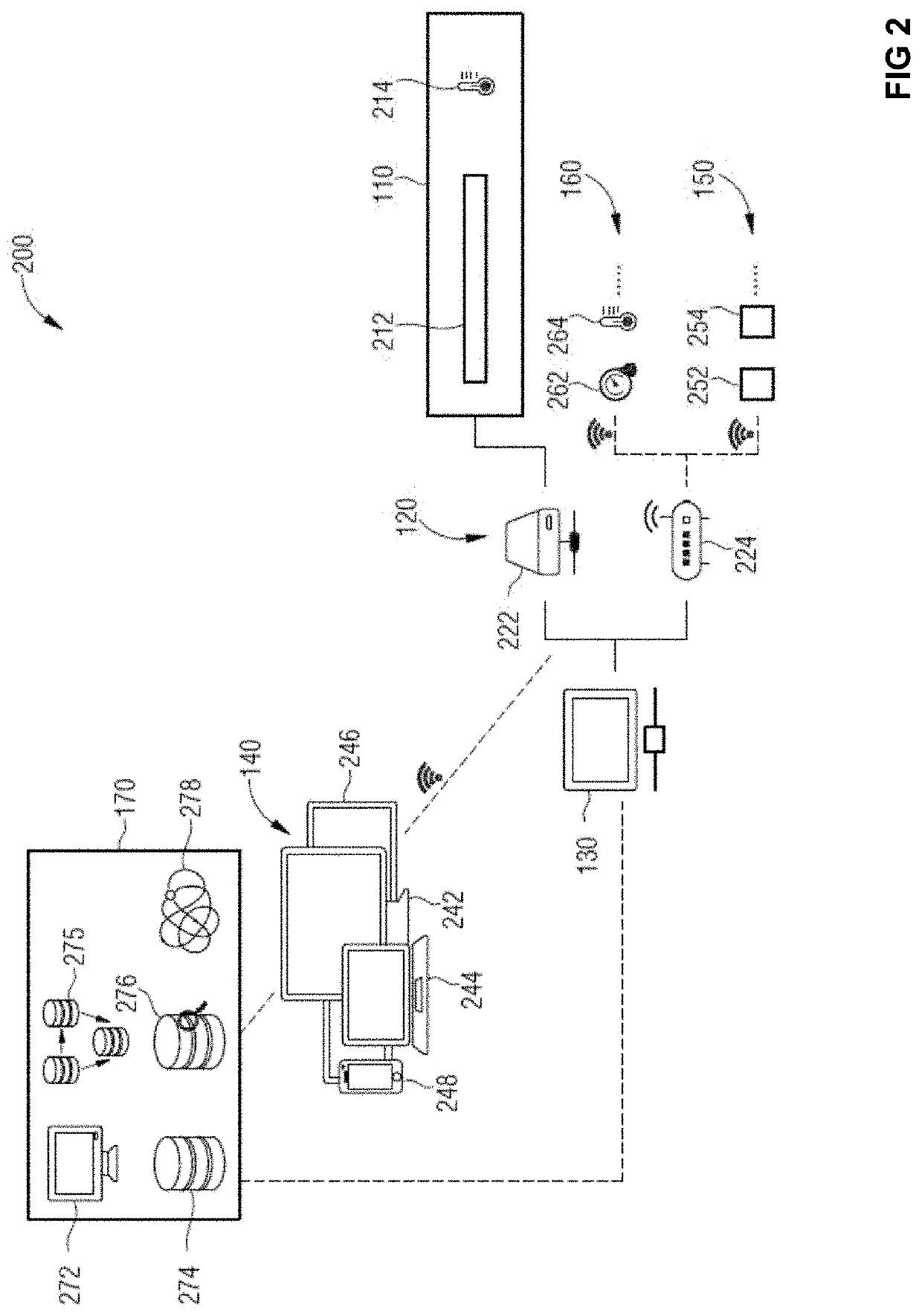
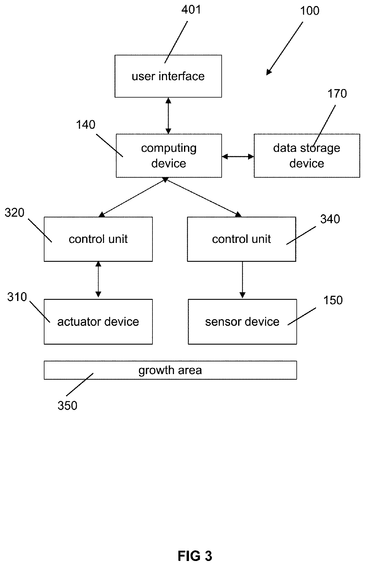

Image

  • Controlled Agricultural Systems and Methods of Managing Agricultural Systems
  • Controlled Agricultural Systems and Methods of Managing Agricultural Systems
  • Controlled Agricultural Systems and Methods of Managing Agricultural Systems

Examples


Embodiment Construction

>The detailed description is described with reference to the accompanying figures. In the context of this description, the terms “connected” and “coupled” are used to describe both a direct and an indirect connection and a direct or indirect coupling.

[2271]System Setup

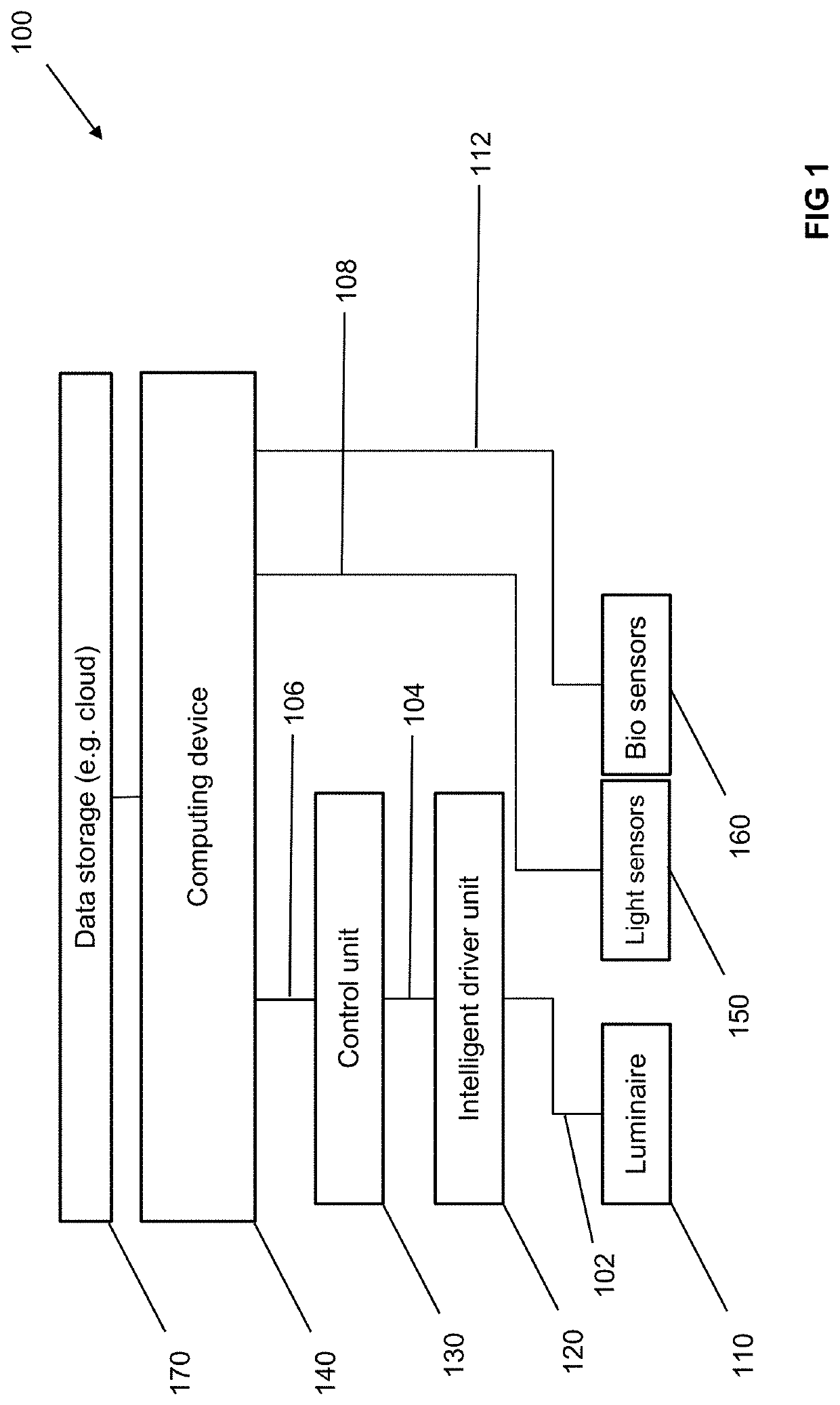
[2272]FIG. 1 illustrates schematically a Controlled Agricultural System 100 according to various embodiments.

[2273]An agricultural light fixture 110 is connected to an intelligent driver unit 120. The intelligent driver unit 120 is configured to transmit a first signal 102 to the agricultural light fixture 110. The connection between the agricultural light fixture 110 and the intelligent driver unit 120 may be a wired connection or a wireless connection. The transmitting signal 102 may conform to a common communication protocol. The intelligent driver unit 120 is connected to a light control unit 130. The light control unit 130 is configured to transmit a second signal 104 to the intelligent driver unit 120. The first ...


PUM


Abstract

The present disclosure relates to different techniques of controlling an agricultural system, as for example a controlled agricultural system, an agricultural light fixture and a method for agricultural management.Furthermore, the disclosure relates to an agricultural system, which comprises a plurality of processing lines for growing plants of a given plant type, wherein a first processing line in the plurality of processing lines is configured to move a first plurality of plants through the agricultural system along a route; and apply a first growth condition to the first plurality of plants to satisfy a first active agent parameter for the first plurality of plants.

Description

CROSS REFERENCE TO RELATED APPLICATIONS[0001]This patent application is a continuation of U.S. patent application Ser. No. 16 / 275,476, entitled “Controlled Agricultural Systems and Methods of Managing Agricultural Systems,” filed Feb. 14, 2019, which is hereby incorporated by reference in its entirety.INTRODUCTION[0002]The present disclosure relates to a Controlled Agricultural System, an Agricultural Light Fixture for use in a Controlled Agricultural System and a Method for Agricultural Management.[0003]Agriculture has been a success story for thousands of years. Technical improvements, from the very first ploughshare to today's state of the art harvesting machines, from the early use of minerals and manure by Egyptians, Romans, and Babylonians to today's tailor-made fertilizers, from early plant breeding to genetic engineering, farming culture allowed for a steady increase of the harvest. In spite of these extensive changes, one underlying principle remained the same, the plant gr...

Claims


Application Information

Patent Timeline
Patent Type & Authority Applications(United States)
IPC IPC(8): G06Q50/02A01B79/00A01C21/00A01G9/029A01G31/02A01G7/04
CPCA01G9/0297A01C21/005A01G7/045A01G31/02A01B79/005G06Q50/02A01G9/247Y02P60/21A01G31/042G06Q10/0639
Inventor BONGARTZ, TIMOOLSCHOWSKI, SEBASTIANHAAS, NORBERTANGENENDT, GUIDOBURZA, MAREKMAGG, NORBERT
Owner FLUENCE BIOENG INC
Learn More