Electronic thermometer
一种电子体温计、筐体的技术,应用在温度计、体温测量、温度计的零部件等方向,能够解决困难、固定温度传感器等问题
- Summary
- Abstract
- Description
- Claims
- Application Information
AI Technical Summary
Problems solved by technology
Method used
Image

Examples
Embodiment 1
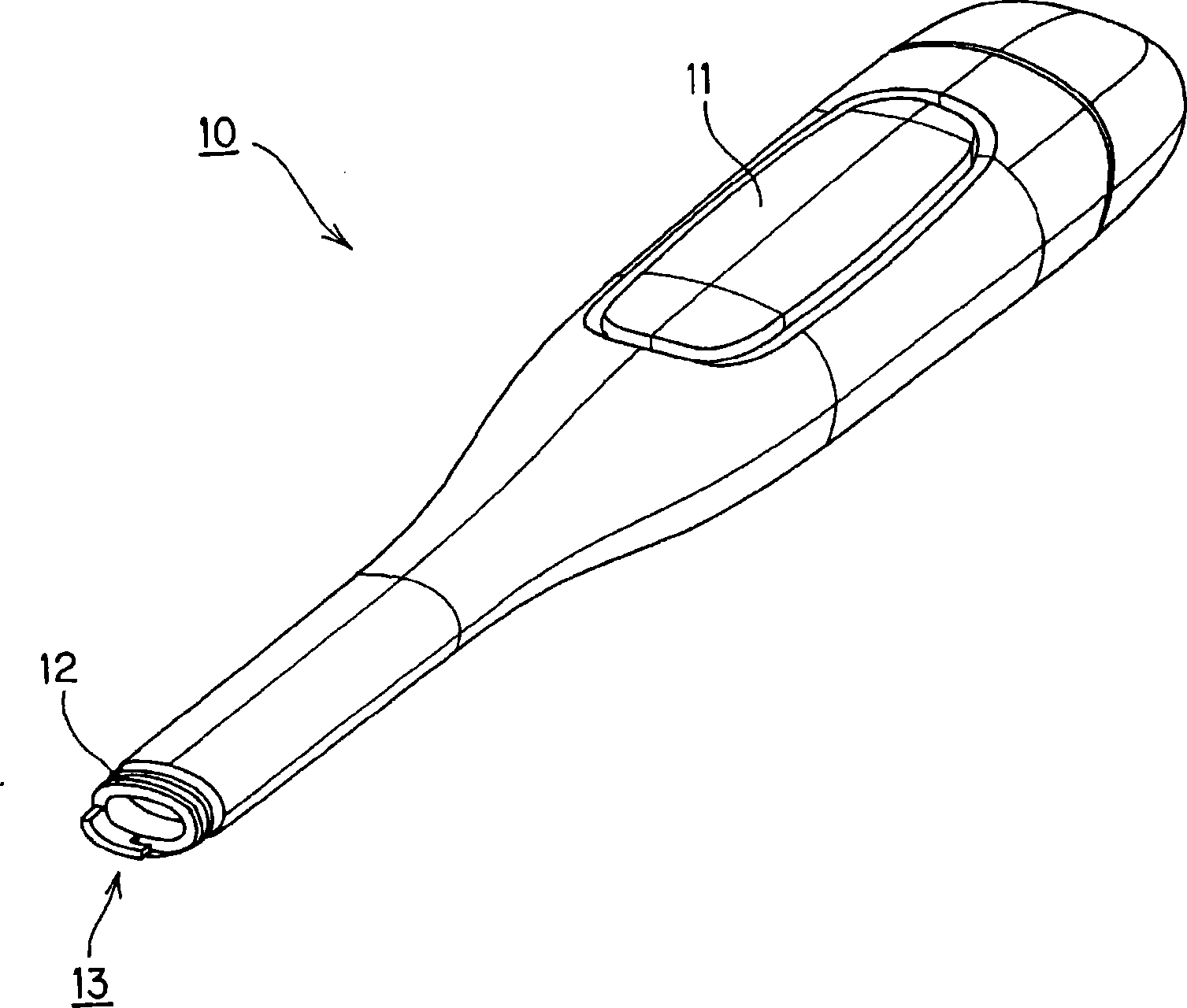
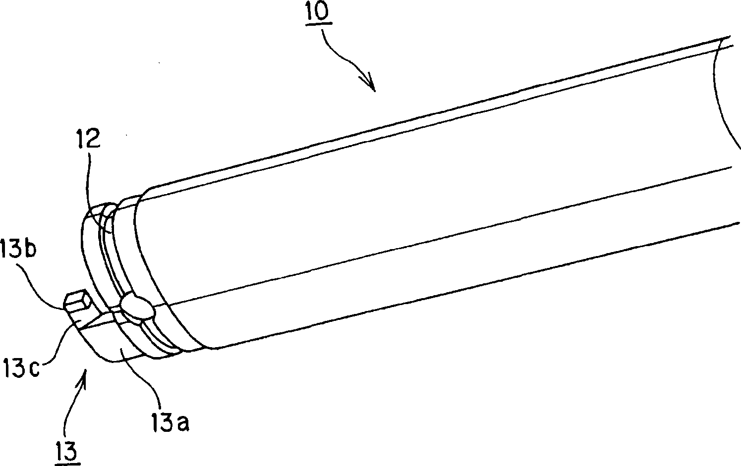
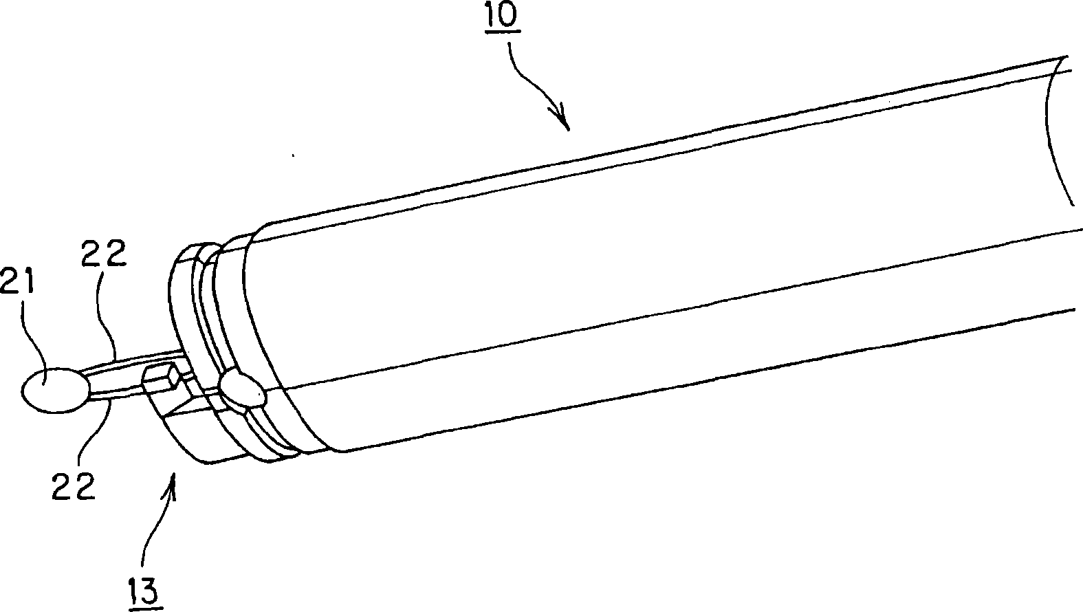
[0080] refer to Figure 1 to Figure 8 , to describe the electronic thermometer of Embodiment 1 of the present invention. figure 1 It is a perspective view of the casing of the electronic thermometer of Example 1 of the present invention. figure 2 It is a perspective view of the vicinity of the front end of the casing of the electronic thermometer according to the first embodiment of the present invention. image 3 It is a perspective view of a state in which a temperature sensor is pulled out from the vicinity of the front end of the casing of the electronic thermometer according to the first embodiment of the present invention. Figure 4 A perspective view showing a state in which a lead wire is held near the front end of the housing of the electronic thermometer according to the first embodiment of the present invention. Figure 5 A perspective view of a state in which a cover is attached to a casing in the electronic thermometer according to Example 1 of the present inv...
Embodiment 2
[0105] Figure 9 Example 2 of the present invention is shown. In this embodiment, a modified example of the lead wire holding portion (extending portion) will be described. The other basic structures and functions are the same as those in Embodiment 1, and descriptions of the same structural parts are omitted.
[0106] Figure 9It is a perspective view of the lead wire holding part (extension part) of Example 2 of this invention. In this embodiment, only the structure of the holding portion (extension portion) of the above-mentioned embodiment 1 is different. In the extension portion 14 of this embodiment, a through hole 14a is provided at the tip of the protruding portion protruding in the longitudinal direction of the casing. The through-hole 14 a is set to a size that allows the lead wire 22 to pass through, but does not allow the temperature sensor 21 to pass through. By passing the lead wire 22 through the through hole 14a in advance, the lead wire 22 can be held whi...
Embodiment 3
[0108] Figure 10 Example 3 of the present invention is shown. In this embodiment, a modified example of the lead wire holding portion (extending portion) will be described. Other basic structures and functions are the same as those in Embodiment 1, so descriptions of the same structural parts are omitted.
[0109] Figure 10 It is a perspective view of the lead wire holding part (extension part) of Example 3 of this invention. In this embodiment, only the structure of the holding portion (extension portion) of the above-mentioned embodiment 1 is different. In the extension portion 15 of this embodiment, the front end of the protruding portion protruding in the longitudinal direction of the casing is formed in a Y shape, and thus a V-shaped V-shaped groove portion 15a is provided at the front end. In addition, in this embodiment, the lead wire 22 is sandwiched by the V-shaped groove portion 15a. Thereby, similarly to the case of the above-described first embodiment, the l...
PUM
 Abstract
Description
Claims
Application Information
 - R&D
- Intellectual Property
- Life Sciences
- Materials
- Tech Scout
- Unparalleled Data Quality
- Higher Quality Content
- 60% Fewer Hallucinations
Browse by: Latest US Patents, China's latest patents, Technical Efficacy Thesaurus, Application Domain, Technology Topic, Popular Technical Reports.
© 2025 PatSnap. All rights reserved.Legal|Privacy policy|Modern Slavery Act Transparency Statement|Sitemap|About US| Contact US: help@patsnap.com