Bed control procedure

A control unit, highly controlled technology, used in hospital beds, medical science, hospital equipment, etc.

Inactive Publication Date: 2008-11-19
KCI LICENSING INC
View PDF1 Cites 4 Cited by
  • Summary
  • Abstract
  • Description
  • Claims
  • Application Information

AI Technical Summary

Problems solved by technology

Therefore, having a bed that can be lowered to a height lower than that used for such devices can be problematic in forcing the caregiver to control the bed height (often visually) until the desired height is achieved

Method used


Image

  • Bed control procedure
  • Bed control procedure
  • Bed control procedure

Examples


Embodiment Construction

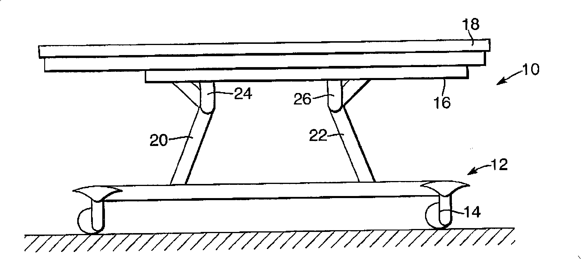
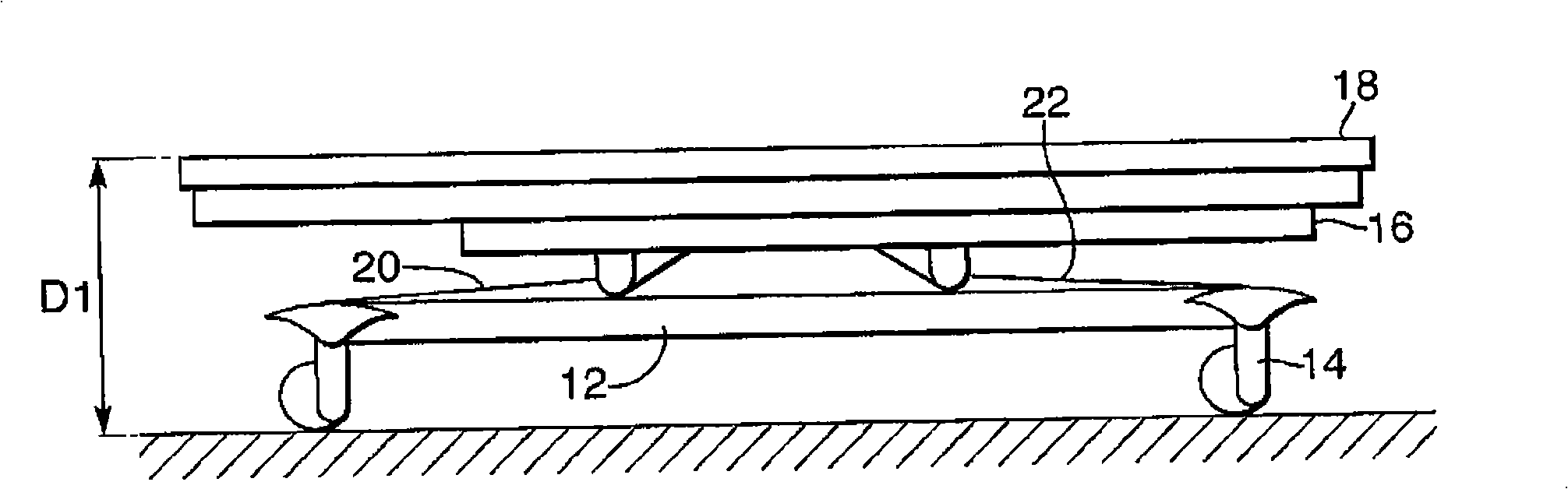
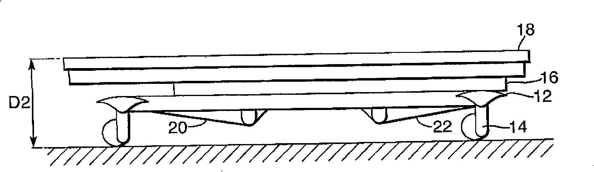
[0019] refer to figure 1 , which shows an embodiment of a bed assembly 10 comprising a wheeled base 12 equipped with four swivel casters 14 , a subframe 16 and a mattress support frame 18 . Subframe 16 supports a plurality of electrically operated actuators ( figure 1 not shown in ), the electrically operated actuators are used to raise and lower the bed 10, and to raise and lower the configurable portion of the mattress support frame 18. The sub-frame and mattress support frame 19 may be of the type known to those skilled in the art, or of the type disclosed in the applicant's co-pending UK application filed on the same day as the present application.

[0020] In this example, the assembly 10 includes first and second pivotable struts 20, 22, the first ends of which are pivotally coupled to the dependent support flanges 24, 26 of the subframe 16, and the second The ends are slidably received in suitable rails (not shown) in the wheeled base frame 12 . Electric controllable...


PUM


Abstract

A bed assembly (10) includes a wheeled base (12), a sub-frame (16) and mattress support frame (18). The sub-frame (16) supports a plurality of electrically operated actuators which provide for raising and lowering of the bed (10). The bed can be lowered to a first low position in which the bed frame (18) is around 38 to 45 centimetres above floor height and to a lower position in which the frame (18) is around 30 centimetres above floor height. The bed is lowered to the first height upon receipt of a first command input and can only be lowered below that first height upon receipt of a second control input distinct from the first control input. Preferably, the bed is lowered at a slower speed from the first low height to its lowermost position.

Description

technical field [0001] This invention relates to bed assemblies, and more particularly to methods for controlling bed height. Background technique [0002] A typical modern hospital bed can be adjusted to accommodate many different configurations and different heights. To achieve adjustment of the bed, a number of electrically operated actuators have been provided. For patient comfort, the patient is able to adjust the configuration of the bed as well as its height. For example, for many nursing procedures involving moving the patient into and out of the bed, the bed may need to be configured in a lie-flat position and may need to be set at a particular height that is uncomfortable for the patient. However, during periods of rest and recovery, the patient may prefer to have the bed configured in a sitting position, and may want to adjust the bed height, for example, to improve interaction with visitors and other patients. [0003] There may also be a need to be able to lo...

Claims


Application Information

Patent Timeline
Patent Type & Authority Applications(China)
IPC IPC(8): A61G7/012A61G7/018
CPCA61G7/012A61G7/018
Inventor 斯蒂芬·海斯斯蒂芬·霍尔约克
Owner KCI LICENSING INC
Why Eureka
Try Eureka