Installation for high pressure compression with several stages

A technology of high-pressure compression and compression equipment, applied in multi-stage pumps, mechanical equipment, liquid fuel engines, etc., can solve the problems of high cost, consumption, and increase of the volume of compression equipment, and achieve the effect of low cost

Active Publication Date: 2008-11-19
ATLAS COPCO CREPELLE
View PDF0 Cites 6 Cited by
  • Summary
  • Abstract
  • Description
  • Claims
  • Application Information

AI Technical Summary

Problems solved by technology

[0011] [11] Another disadvantage of the known multi-stage compression equipment is that the first reservoir between the two compressors is relatively large in order to prevent the first A reservoir filled with gas is fully consumed before the first compressor is loaded
[0012] [12] Apparently, a large size accumulator of this type pre-installed between the compressors increases the volume of the compression equipment and in fact makes the compression equipment more expensive

Method used


Image

  • Installation for high pressure compression with several stages
  • Installation for high pressure compression with several stages

Examples


Embodiment Construction

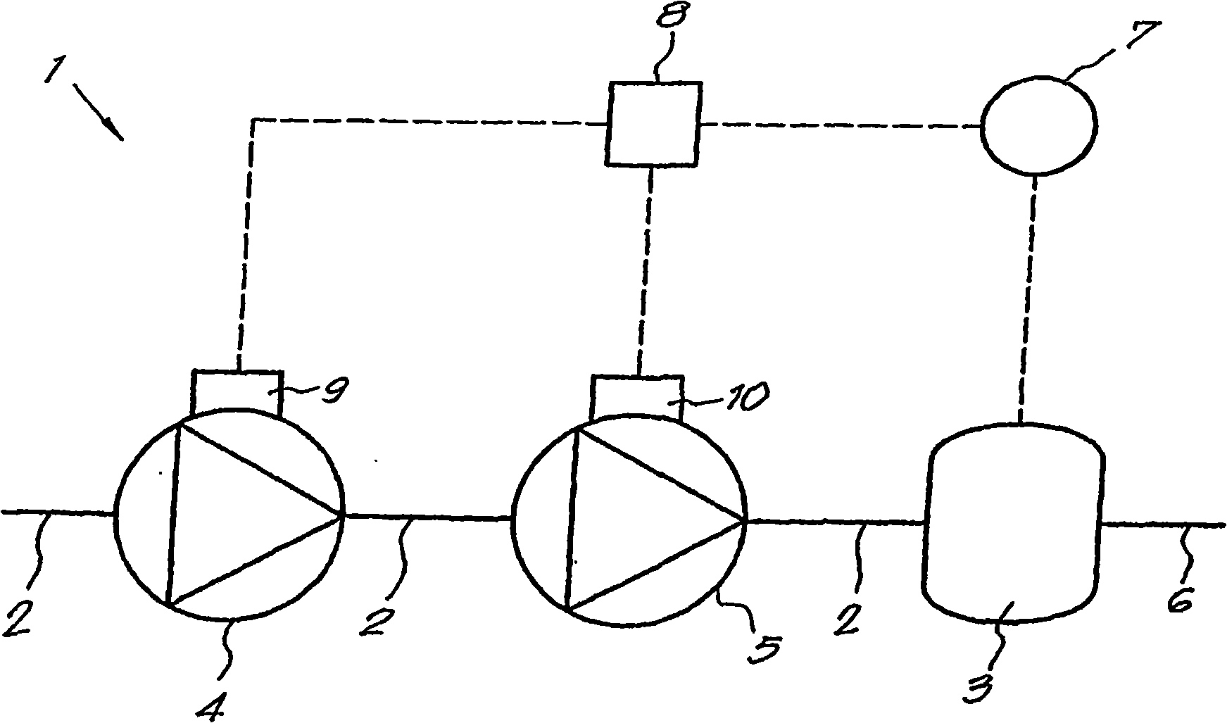
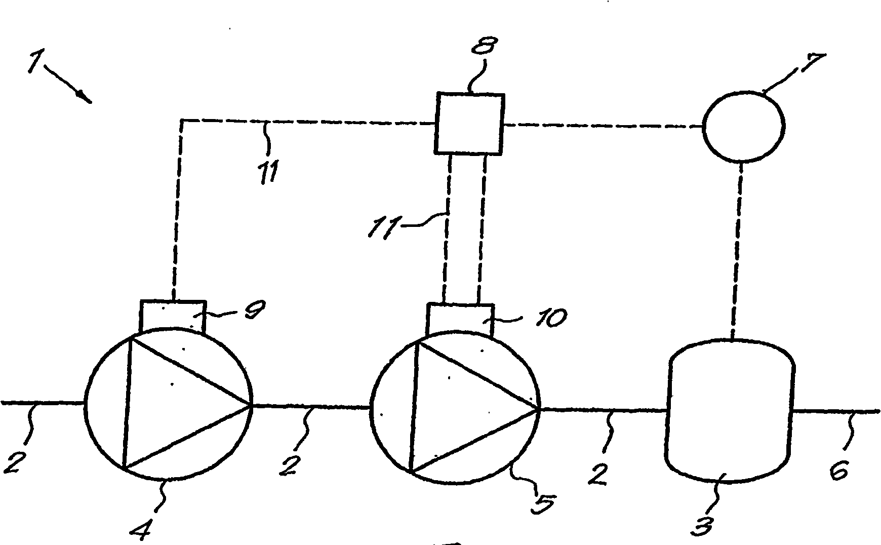
[0023] [23] If figure 1 As shown, a multistage high-pressure compression plant 1 according to the invention essentially comprises a main gas line 2 leading to a buffer 3, in this case two volumetric compressors 4 and 5 installed in series In the pipeline 2.

[0024] [24] The first compressor 4 is for example a screw compressor (compresseur à vis) for the low-pressure compression stage, while the second compressor 5 - also called a booster compressor - is for example a piston compressor Compressors for high pressure compression stages.

[0025] [25] The aforesaid buffer 3 may be a storage or similar connected to the user network 6 and preferably provided therein with means 7 which make it possible to determine the gas pressure of the filling in said storage, and Said component 7 is connected to a control box 8, which is, for example, an electronics box.

[0026] [26] Of course, the above-mentioned components 7 designed to determine the pressure can also be installed at the o...


PUM


Abstract

The invention concerns an installation for high pressure compression with several stages, normally used for producing PET bottles. The inventive installation comprises a main pipe (2) emerging in a baffle plate (3), wherein at least two compressors (4, 5) are mounted in series each having its own drive member (9, 10). The installation is equipped with means (7) for determining the pressure at the output of the main pipe (2), said installation being connected to a control box (8). Typically, the control box (8) is connected to at least two of the drive members (9, 10) of the compressors (4, 5) and ensures monitoring of said compressors such that the latter rotate jointly whether charged or uncharged. Thus, the compressors (4, 5) are jointly charged based on the pressure prevailing in the baffle plate (3), such that the charging of the compressor representing the overpressure stage, the compressor(s) of the lower compression stages are automatically and jointly charged.

Description

technical field [0001] [01] The present invention relates to multi-stage high-pressure compression equipment comprising at least two compressors connected in series by a pipeline. Background technique [0002] [02] High-pressure equipment of this type is used, for example, in the field of producing polyethylene terephthalate (PET) bottles, which require the use of compressed gas at pressures in excess of 2000 kPa. [0003] [03] It is known that in order to achieve a gas pressure of 2000 kPa or higher, two volumetric compressors are installed in series, and a first gas reservoir is preset at the outlet of the first compressor, the reservoir The outlet of is connected to the inlet of the second compressor, which is a booster compressor. [0004] [04] At the outlet of the above-mentioned booster compressor, it is generally preferred to preset a second storage, which acts as a buffer for the user network. [0005] [05] In known multi-stage compressors of this type, the driver ...

Claims


Application Information

Patent Timeline
Patent Type & Authority Applications(China)
IPC IPC(8): F04B49/02F04B25/00
CPCF04C23/005F04B25/00F04B41/02F04B41/06F04B49/065F04B2205/05F04C18/16F04C23/001F04C28/02F04C28/08F04C2270/18F04C2270/56
Inventor P·M·A·勒隆H·T·马吉茨
Owner ATLAS COPCO CREPELLE
Why Eureka
Try Eureka