
Eureka
For R&D, Eureka makes reading and utilizing patents & technical documents easy.
Eureka AIR
Designed for self-driven R&D workflows. Generate viable solutions, solve complex R&D challenges, empower your innovation with AI.

Eureka Materials
Designed for material experts only. Revolutionize your material R&D, from search, analyze, to developing new materials.

TechResearch
Generate reliable direction feasibility study reports for your R&D in just a few steps.

TechSeek
Discover and master advanced knowledge NOW. Basics, ideas, possibilities, all at once.

TechMind
As an expert in R&D Theories, TechMind can generates customized viable solutions instantly.

TechRisk
Analyze your overall solution with one click, know your potential R&D risks in advance.

TechMonitor
Get weekly tech updates, stay abreast of the latest tech innovations and key insights.
Lordosis support
A technology of support and support structure, applied in the direction of vehicle parts, special positions of vehicles, chairs, etc.
- Summary
- Abstract
- Description
- Claims
- Application Information
AI Technical Summary
Problems solved by technology
Method used
Image

Examples
Embodiment Construction
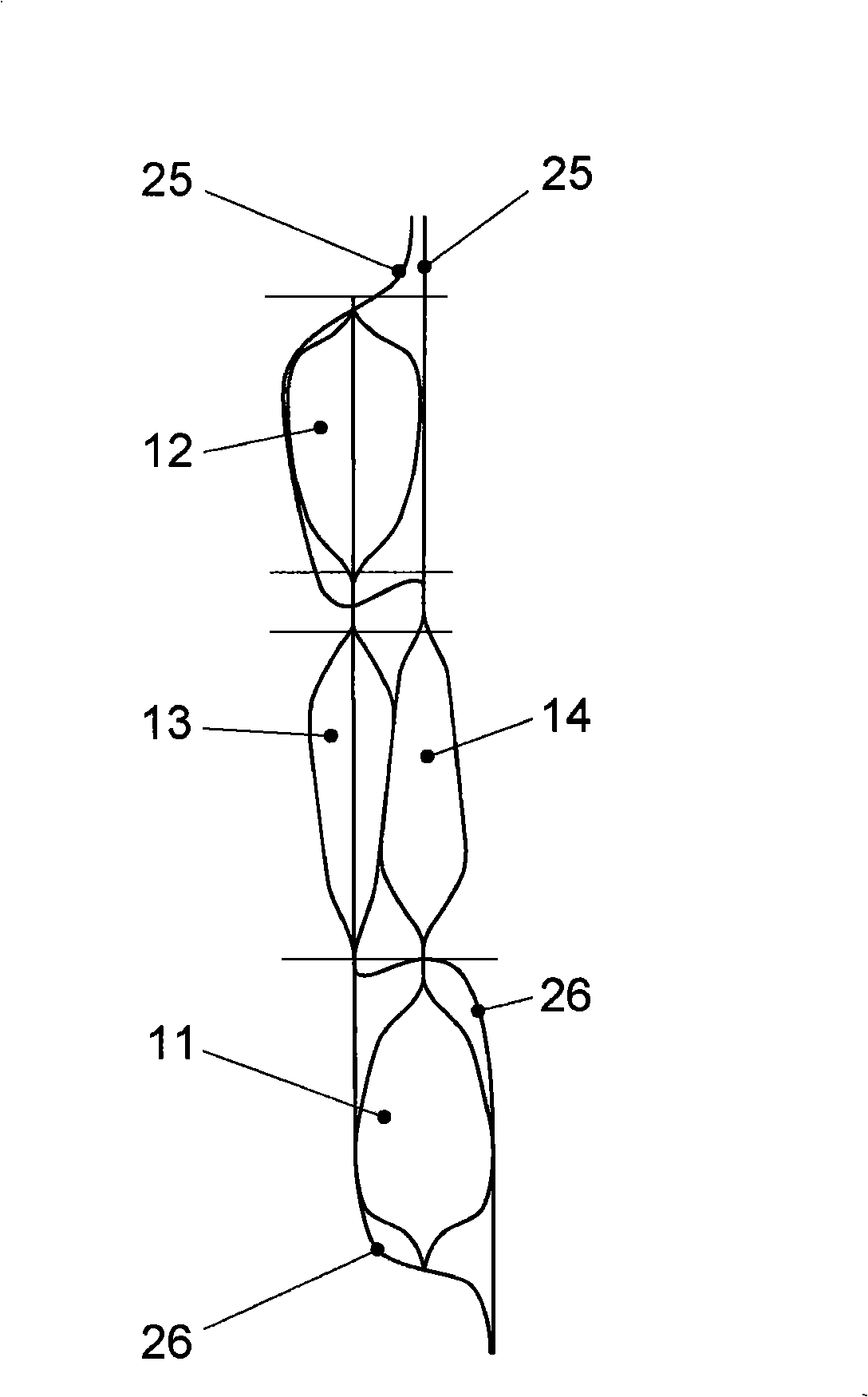
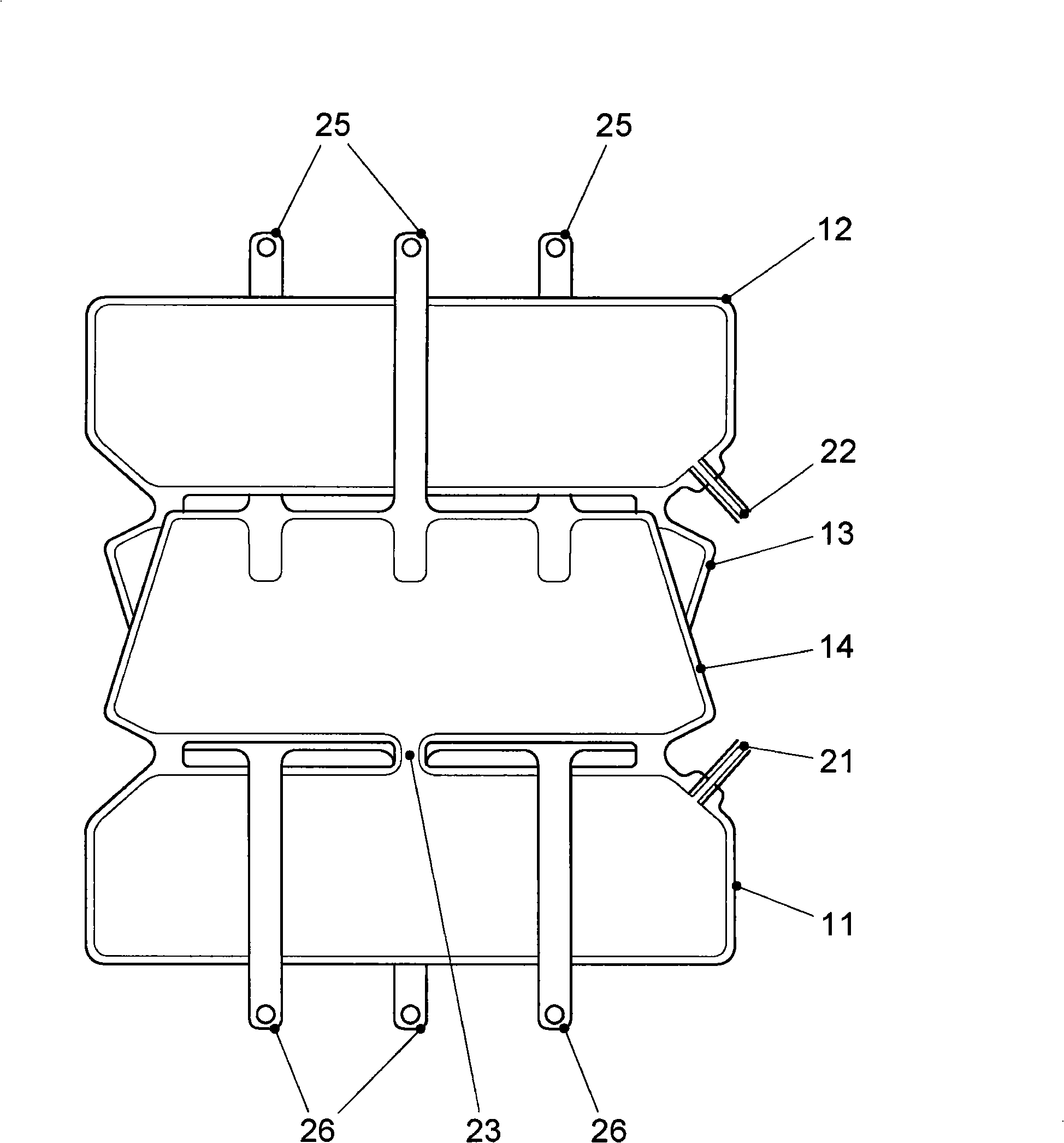
[0019] Such as figure 1 As shown, the lumbar support comprises two external pneumatically operated first chambers 11 and 12 , these being a lower chamber 11 and an upper chamber 12 . The two outer cavities 11 and 12 each have an air connection to one of the two central second cavities 13 , 14 positioned above each other perpendicularly to the longitudinal direction of the lumbar support. as (especially) figure 2 As shown, in each case, the lower chamber 11 and the upper chamber 12 comprise air supply lines 21 and 22, respectively, by means of which air supply lines 21 and 22 are used to control the supply of air to or from the chambers 11 and 12. remove the air. exist figure 2 In the representation shown, chamber 11 is connected to supply air to chamber 14 via connection 23 . Likewise, cavity 12 includes an air connection (not shown) to cavity 13 . If the chamber 12 is then fed with compressed air via the air supply line 22 , the chamber 12 is filled with compressed air...
PUM
 Abstract
Description
Claims
Application Information
 - R&D Engineer
- R&D Manager
- IP Professional
- Industry Leading Data Capabilities
- Powerful AI technology
- Patent DNA Extraction
Browse by: Latest US Patents, China's latest patents, Technical Efficacy Thesaurus, Application Domain, Technology Topic, Popular Technical Reports.
© 2024 PatSnap. All rights reserved.Legal|Privacy policy|Modern Slavery Act Transparency Statement|Sitemap|About US| Contact US: help@patsnap.com